- home
- Media center
- Articles
- How to adjust valves on a T-40 tractor
Menu
- News
- Articles
- Video materials
- Photo materials
- Publication in the media
- 3D tour
29.04.2021
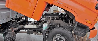
The T-40 tractor is a vehicle used in agriculture and transport. It is actively used for plowing with seedling processing, mowing, hayloft cleaning, stacking, snow clearing, bulldozing and transport. It is characterized by an increased level of cross-country ability, good maneuverability, adjustable track and clearance. All the work is performed by the motor in four cycles.
The execution of a 4-stroke cycle in the T-40 engine cylinder is ensured by the installation of gas redistribution. Motor functioning with other tractor mechanisms depends on the correctness of its operation. To prevent engine and timing belt malfunctions, it is recommended to adjust the valve mechanisms after 15,000 kilometers of uninterrupted engine operation. Adjusting the valves on the T-40 tractor is performed by both a professional and a beginner.
Operating principle of the timing belt
The timing belt includes a shaft, gas redistribution gears, and a valve mechanism with a drive. The timing mechanism is started by the crankshaft mechanism of the engine. Through a gear system, it transmits the moment of force to the shaft. It forms pressure on the cylindrical valve mechanism and covers the pressure.
After the shaft turn and the fist exits the pusher installation, the valve under the spring device is placed in the area and covers the passage in the cylindrical installation. Intake occurs when the intake duct opens. The release occurs through the release component.
By choosing the correct operating mode in the installation, a mixture of gasoline and diesel is mixed in a proportional ratio in a cylindrical system. The engine starts up successfully and runs smoothly. Possible malfunctions are indicated by an unusual shade of exhaust gas, a decrease in motor power, an operational interruption, or difficult engine starting.
Operating principle of the gas distribution device
Main details:
- camshaft;
- timing gears;
- valve mechanism with drive.
Adjusting the valves is necessary for the correct operation of the tractor.
The operation of the timing belt is started by the engine crankshaft. Through a system of gears, it transmits torque to the camshaft, the cam of which creates pressure on the cylinder valve, which opens as a result of this pressure. When the camshaft rotates and the cam leaves the tappet, the valve springs into place and closes the hole in the cylinder cover. Air is admitted when the intake valve opens, and air is released through the exhaust valve. When the mechanism operates correctly, the air-fuel mixture is mixed in the required proportions in the cylinders, and the engine starts successfully and runs without interruption.
Possible malfunctions may be indicated by an unusual color of exhaust gases, a decrease in engine power, interruptions in its operation, and difficulty starting the engine.
Valve settings
During operation, the valve parts change their position in height by quarters of a millimeter. Due to the low rise in passage, clearance is required between the valve stem parts. Tractor valves are adjusted through a special type of adjusting screw. As it is screwed in, the arm of the lever valve increases and part of the gap decreases. During unscrewing, the opposite situation occurs. It is necessary to understand that the intake gap should be less than the exhaust, since the system heats up more strongly.
The gap is checked using a special probe. It should be equal to 0.3 mm. The test is carried out with the engine not running. In addition to clearance adjustment, maintenance includes examining the tightness of the valve fit to the seat components.
How to adjust the T-40 valve?
Before adjusting the valves on the T-40 tractor, you must perform the following steps:
- For ease of operation, it is recommended to move the cardan shaft to the side. To do this, it is necessary to remove a number of holding devices and pull the shaft with the steering mechanism.
- Place the piston of the new cylinder in the compression stroke position. This is done by aligning the marks at the top of the point with the fan pulley indicator. Cover several valve systems.
- Loosen the adjusting screw nut and set the screw gap. Be sure to use a dipstick.
- Tighten the control nut, measure the gap again, and turn the rod.
- Turn the crankshaft half a turn clockwise to adjust the cylinder valves.
- Adjust the T-40 valves as follows in terms of sequence: 1, 3, 4, 2.
All types of work should be performed on a cooled engine. On a working engine, the valve size changes unevenly. The outlet becomes larger than the inlet. This will lead to measurement inaccuracies in a unique way. Before work, you should watch a video aimed at adjustment. Prepare tools in advance: wrenches with a 0.3 mm feeler gauge.
Ignition adjustment
If you want to properly adjust this type of mechanism, it is important to note that the ignition system, which is familiar to vehicles with a gasoline-type internal combustion engine, is not available on diesel analogues. Instead of adjustment, you will need to set the injection timing on the T 40 tractor, since in diesel engines the fuel ignites due to excess pressure.
Installation and adjustment of injection timing
When planning to configure such a unit yourself, you will need to prepare a standard set of tools, as well as a special glass tube, the internal diameter of which is 0.1-0.15 cm. To avoid mistakes, you should follow the simplest instructions:
- Disconnect the high pressure pipe from the fitting of the 1st cylinder.
- Place the prepared glass tube on it.
- Turn the crankshaft until the “T” indicator on the cover aligns with the “NDT” position, which can be found directly on the crankshaft pulley.
- Remove the filler neck, and then remove the pump fasteners.
- Set the control lever to the full feed position, then turn out the fuel pump adjusting element until fuel free of air impurities appears in the tube.
- Drain the fuel and note the moment it rises.
- Having installed the pump shaft in the desired position, it is necessary to tighten the bolts so that the holes on the flange coincide with similar objects on the gears.
- Check system functionality.
Be sure to read: Pump MTZ 80
Using such an algorithm, you can easily adjust the injection timing, but after each adjustment it is necessary to check the operation of the system, since the optimal position often shifts when the bolts are fastened.
Adjustment of valves
Among the necessary manipulations carried out as part of the maintenance of model T-40 tractors is checking and adjusting the valves. During the work, you need to make sure that there is a normal amount of lubricant on the camshaft, as well as that the elements are tightly fastened in their positions.
Tractor gas distribution
The need for maintenance occurs every 380 hours of continuous operation, otherwise there is a high probability of deviations from the norm and serious malfunctions. According to the rules, the valve clearance on a cold power unit should be 0.3 mm, both for the exhaust and intake elements.
The valve adjustment algorithm is extremely simple and involves performing the following manipulations:
- Remove the rear universal joint wedge and then release it.
- Adjustment of the gaps is carried out using a special adjusting screw located on the rocker arm.
- A feeler gauge is used to monitor the current gap and set the required values.
- Rotate the piston of cylinder 1, setting it to the end of stroke position, aligning the mark with the pointer.
- Loosen the locknut, then set the required clearance, and then tighten it again.
- The valves are adjusted according to the order of operation of the cylinders; when moving to the next element, you will need to turn the crankshaft 0.5 turns.
When carrying out work, it is extremely important to ensure that the locknut is securely fastened, otherwise over time this will lead to a shift in the gap, as well as other problems.
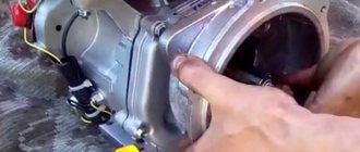
Tractor decompressor
The decompressor is a small, but fundamental mechanism for the operation of the engine, which ensures free engine start in cool weather and a quick suspension of the movement process. Problems with its functioning are associated with incorrect valve settings.
The device includes a lever kit that connects to the rail. Their ends fit into the pusher grooves of the intake valves. Ultimately, the movement of the mechanism entails the movement of the subsequent one. During decompression problems, you need to check the wear of the bushings and the integrity of the rocker arms.
The valve clearance must be measured with the engine not running. Then the indicators will be accurate. A gap of 0.3 mm is considered ideal. It must be measured with a feeler gauge.
When do you need to adjust your tractor valves?
In the absence of long-term, continuous use of the tractor engine, the valves can serve without repair throughout the entire service life. To avoid their breakage or breakage during recessing, they should be dismantled and replaced in a timely manner. If it is necessary to replace gears, parts should be inserted into the clutch only according to the scheme provided by the manufacturer. A mechanism in the form of a decompressor is required to start a cold engine. A decompressor is necessary when the engine is rapidly braking. It runs on diesel. This mechanism is a combination of several control pairs: manual and rack and pinion. The levers are rigidly attached to the forks.
Operating procedure for the T-40 tractor
It is very important to set the fuel injection correctly. In this case it is necessary:
- unfasten the high pressure tube;
- attach the glass tube;
- bring the element to the desired position (the T indicator is combined with the technical documentation);
- remove the pumping system from the mount;
- move the fuel supply lever to the channel characterized by full supply;
- allow the crankshaft to rotate until the fuel is supplied cleanly, without bubbling;
- remove the fuel part from the tank, record the period of fuel increase.
Then it remains to check how the fuel system works.
Modifications
With D-37 engine
The base model has rear-wheel drive. Its modifications are made with all-wheel drive:
- T-40A – presence of a front axle. Front-wheel drive engages automatically in accordance with driving conditions;
- T-40AN - the tractor is adapted for working on a steep slope, the height and ground clearance are less than the basic version;
- T-50A is an industrial modification, adapted for a single-bucket loader.
With D-144 engine
The T-40M has rear-wheel drive, while the modifications have all-wheel drive:
- T-40AM - unlike the T-40M - front axle with drive;
- T-40ANM - a powerful analogue of the T-40AN: reduced ground clearance for working on a steep slope (up to 20 degrees), lower height, greater stability;
- T-40AP is an industrial model, adapted for working with road equipment.
Expert advice
There are known problems with such mechanisms. Often, T-40 owners encounter situations with a long engine start and increased exhaust frequency. The main root cause is considered to be a lack of tightness of the valve and seat. To fix the damage, you need to dismantle the head and then grind the valve with a machine. This problem is caused by incorrect installation of the motor gear.
To perform any work with the engine, you must be careful. It is not difficult to perform valve adjustment on the T-40 tractor, so any novice master will do the job. The tractor is developed taking into account repairs in difficult field conditions. Therefore, repair work will require careful handling and strict adherence to the attached diagram.
Gas distribution mechanism
Before figuring out how to set the ignition on a T 40 with a fuel injection pump from MTZ, it is advisable to familiarize yourself in more detail with the structure of the gas distribution system of this popular tractor model. The timing belt of the unit is a special unit designed to create optimal conditions for engine operation. Among the most significant elements of its design it is worth noting:
- camshaft;
- gear mechanism;
- valve system and its drive, including springs, rods, pushers, springs;
- fasteners.
An important element of the tractor design, which is necessary for its successful start in low temperature conditions, is the decompressor. In addition to the start, it actively participates when it is necessary to urgently stop the engine. The main elements of its design are levers, slats, and hinges.
Timing gear diagram