- home
- Media center
- Articles
- Kamaz PGU malfunctions
Menu
- News
- Articles
- Video materials
- Photo materials
- Publication in the media
- 3D tour
28.04.2019
The pneumohydraulic booster (in other words, PGU) is part of the Kamaz composite clutch unit. Similar to a conventional power steering, which makes it easier to turn the steering column, the PSU allows you to apply less effort when pressing the clutch pedal.
The specifics of truck transport require the complexity of controlling the mechanisms. Among other things, the driver sometimes has to make additional efforts to control the tractor. That is why designers have come up with many upgrades to reduce physical activity to a minimum.
The body of the device is reinforced with two types of metal: the front part is aluminum, the back part is cast iron. A sealing connecting gasket is laid between the two parts, ensuring the best tightness.
In ordinary cars, a clutch that is difficult to press must be replaced because it is either burned out, or the cable is jammed, or the basket has “flyed.” However, the cargo clutch was always pressed harder than the passenger clutch. Pneumohydraulics significantly facilitate the moment of squeezing the accelerator. A small, but such an important detail, has the following components:
- The tracking system is a special mechanism that transmits information to the central electronic unit. Initially, the clutch pedal is in a hard position, it is the tracking system that transmits the pressing impulse, after which the process of squeezing the accelerator becomes easier.
- The executive pneumatic cylinder is the heart of the system and performs a mechanical function.
- Driven disc lining wear indicator - transmits information about the current technical condition of the system.
Of course, hydraulics is unthinkable without hydraulic fluid. It forms the basis of the system and is transported between the components of the mechanism under high pressure, creating the necessary torque. Location: master cylinder. The pneumohydraulic cylinder forces the pistons to work together with the servo system. After the pressure is reduced, the parts return to their original position. Actually, the operating principle is identical to almost all Kamaz cylinder mechanisms: high pressure - push, low pressure - initial position. This is why the presence of hydraulic fluid in the system is so important; without it, it is impossible to operate the mechanism.
Kamaz PGU malfunctions
The pneumohydraulic booster (in other words, PGU) is part of the Kamaz composite clutch unit.
Similar to a conventional power steering, which makes it easier to turn the steering column, the PSU allows you to apply less effort when pressing the clutch pedal. The specifics of truck transport require the complexity of controlling the mechanisms. Among other things, the driver sometimes has to make additional efforts to control the tractor. That is why designers have come up with many upgrades to reduce physical activity to a minimum.
The body of the device is reinforced with two types of metal: the front part is aluminum, the back part is cast iron. A sealing connecting gasket is laid between the two parts, ensuring the best tightness.
In ordinary cars, a clutch that is difficult to press must be replaced because it is either burned out, or the cable is jammed, or the basket has “flyed.” However, the cargo clutch was always pressed harder than the passenger clutch. Pneumohydraulics significantly facilitate the moment of squeezing the accelerator. A small, but such an important detail, has the following components:
- The tracking system is a special mechanism that transmits information to the central electronic unit. Initially, the clutch pedal is in a hard position, it is the tracking system that transmits the pressing impulse, after which the process of squeezing the accelerator becomes easier.
- The executive pneumatic cylinder is the heart of the system and performs a mechanical function.
- Driven disc lining wear indicator - transmits information about the current technical condition of the system.
Of course, hydraulics is unthinkable without hydraulic fluid. It forms the basis of the system and is transported between the components of the mechanism under high pressure, creating the necessary torque. Location: master cylinder. The pneumohydraulic cylinder forces the pistons to work together with the servo system. After the pressure is reduced, the parts return to their original position. Actually, the operating principle is identical to almost all Kamaz cylinder mechanisms: high pressure - push, low pressure - initial position. This is why the presence of hydraulic fluid in the system is so important; without it, it is impossible to operate the mechanism.
What is a PGU on a truck?
To control the clutch in KAMAZ trucks, a pneumatic-hydraulic booster (PGU) is used - this device makes it easier to disengage the clutch and reduces driver fatigue. Read about how the KAMAZ PGU is designed and operates, as well as about its maintenance and some of the nuances of repair in this article.
What is Pgu man?
The pneumohydraulic booster (PGU) is part of the clutch assembly, thanks to which minimal effort is required to press the pedal. The solution to a tight pedal motion lies in the repair or complete replacement of the PSU.
Breakdown options
Any mechanism has its own resource, therefore, breakdowns are inevitable. Some car parts are replaced as planned after traveling a certain mileage. The clutch is a specific “organ” of the car that is constantly used. Moreover, the service life directly depends on the conscientious and careful attitude of the driver. If you squeeze the accelerator carelessly, throw it, or don’t press it all the way, you can quickly “burn the clutch” or damage the PSU. Technically, these problems can be reduced to several points.
- The rubber ring or cuff swells, and accordingly, the PSU follower piston jams. A jammed part, designed to be in constant motion, naturally stops in one position, therefore slowing down the operation of the entire system.
- A damaged intake valve produces too little compressed air. Air flows help the system create the necessary pressure, the absence of which leads to breakdown.
- Air inside the hydraulic drive disrupts circulation. The driver may feel an excessive amount of air in the form of sagging of the clutch pedal.
Due to the fact that the basis of the operation of the CCGT is musculoskeletal moments occurring under high pressure, subsidence of soft rings, cuffs, lack of air or its presence in the wrong places lead to breakdowns of the entire system, disrupting the operation of the CCGT.
Design and principle of operation
Pneumohydraulic amplifiers (PGU) are produced in several modifications, differing in the location of the lines and the design of the working rod and protective cover.
The CCGT device includes the following parts:
- a hydraulic cylinder installed under the clutch pedal, together with a piston and a return spring;
- the pneumatic part, which includes a piston common to pneumatics and hydraulics, a rod and a return spring;
- a control mechanism equipped with a diaphragm with a release valve and a return spring;
- valve mechanism (for intake and exhaust) with a common rod and an elastic element to return the parts to the neutral position;
- lining wear indicator rod.
To eliminate gaps, the design has preload springs. There is no play in the connections to the clutch control fork, which allows you to monitor the degree of wear of the friction linings. As the thickness of the material decreases, the piston is recessed into the depth of the amplifier body. The piston acts on a special indicator that informs the driver about the remaining clutch life. Replacement of the driven disk or linings is required when the indicator rod reaches a length of 23 mm.
The clutch booster is equipped with a fitting for connection to the standard pneumatic system of the truck. Normal operation of the unit is possible at a pressure in the air lines of at least 8 kgf/cm². To attach the PGU to the truck frame, there are 4 holes for M8 studs.
Operating principle of the device:
- When you press the clutch pedal, force is transferred to the piston of the hydraulic cylinder. At the same time, a load is applied to the piston group of the follower rod.
- The follower automatically begins to change the position of the piston in the pneumatic power section. The piston acts on the control valve of the follower device, opening the air supply into the cavity of the pneumatic cylinder.
- Gas pressure provides force on the clutch control fork through a separate rod. The tracking circuit automatically adjusts the pressure depending on the force of pressing the clutch pedal with your foot.
- After releasing the pedal, the fluid pressure is released, and then the air supply valve closes. The piston of the pneumatic section returns to its original position.
Symptoms of a problem
The clutch of a truck is complex enough to trust its diagnosis and subsequent repairs only to qualified specialists from certified service centers. Repairing a PSU on your own is not an easy task due to the presence of many small parts, but with clear instructions, even a beginner can try his hand at debugging the operation of a PSU. Diagnostics of pneumohydraulics is rarely carried out, so the main malfunctions are identified visually through the first signs.
- When starting to move or changing gear, the driver will feel the system start working late. For example, initially the pedal is pressed hard, then it becomes easier, and it reaches the “floor” softly. A working mechanism works stably throughout the entire pedal stroke.
- Sometimes, in order for the device to react, you have to press the pedal harder than usual. Of course, this indicates a malfunction, because pressing should initially be smooth.
- The most popular diagnostic mark is “jamming” or “biting” of the clutch. This problem can easily be confused with a cable wedge.
Having detected at least one sign, it is necessary to immediately diagnose the pneumohydraulic drive system.
Specifics of Wabco CCGT
The Wabco pneumatic hydraulic booster (PGU) consists of the following components:
- hydraulic housing;
- hydraulic piston;
- hydro-cuff;
- clutch lining wear indicator;
- indicator washer;
- lining wear indicator housing;
- compression spring;
- pneumatic piston;
- executive pneumatic cylinder;
- case;
- stock;
- drainage tube;
- tracking system.
Any element of the CCGT system can fail over time. But according to statistics, the service center is most often contacted with several standard types of malfunctions and breakdowns.
Repair
There are a lot of Kamaz service centers, each equipped with special diagnostic equipment and fault detection. If the fault is identified by the driver himself, there is the possibility of self-repair, let’s look at a small algorithm for carrying out repair work on the PSU.
- We secure the rear body with a vice, ensuring complete immobility of the part.
- We unscrew the bolts.
- Remove the air valve inlet cover and take out the valve itself.
- Remove the front housing completely.
- Remove the diaphragm springs.
- We remove the diaphragm.
- We empty the rear housing: take out the ring and pistons.
- Unscrew the cover of the outlet seal and bypass valve.
- We remove the vice.
- Pull out the retaining ring.
- Remove the cones, washers, and seat from the valve stem.
- The follower piston releases from the sealing ring.
- The sealing ring is pulled out along with the pneumatic piston, and we dismantle the cuff.
- Removed parts must be thoroughly washed. Kerosene and gasoline are suitable for washing. The washed parts are blown with compressed air and are damaged.
- After carefully examining the spare parts and replacing unsuitable parts, assembly is carried out in the reverse order.
We can draw a simple conclusion: assembling/disassembling a PSU is a very painstaking task, but if you follow the process technology, it is quite possible to do it yourself.
_______________________________________________________________________________
Repair of pneumatic hydraulic booster and clutch master cylinder for Kamaz vehicles
Disassembling the pneumatic hydraulic booster (PGU) KamAZ-4310, 55111, 43118, 5320 - Install the PGU in a vice, clamping the rear housing 55 (Fig. 1) - Unscrew the bolts 4 with washers 3 and remove the air supply cover 5 - Remove the valve 7 of the amplifier assembly from front casing of the pneumatic booster - Unscrew bolts 2 and 23 with washers 1 and remove the front casing 25 assembled with the pneumatic piston 29 - Remove the membrane spring 27 and the pneumatic piston spring 46 - Remove the diaphragm 17 of the Kamaz-4310, 55111, 43118, 5320 PGU assembly - Unscrew the follower piston 33 with housing 31 from the rear housing 55 of the amplifier - Remove the thrust ring 45 and the clutch release piston 59 assembly from the rear housing 55 of the amplifier and the seal housing 43 - Unscrew and remove the bypass valve 48 of the rear housing assembly with cap 47 - Unscrew the breather 49 fastening the exhaust hole cover, remove the cover and seal of the outlet hole of the PGU Kamaz-4310, 55111, 43118, 5320 - Remove the rear housing of the Kamaz clutch pneumatic booster from the vice - Remove the retaining ring 50 of the rear amplifier housing - Unscrew the nut 8 of the valve rod 15 - Remove from the rod 15 valve washer 9 large, cone 10, washer 11 small, valve seat 12, spring 18, tube 14, large washer P, cone 10 and small washer 11 of the valve - Unlock at one point and unscrew the nut 18 of the gearbox membrane - Remove from the seat 22 washer 19 membranes 20 I tabs 21 - Remove the sealing ring 35 from the body 31 of the follower piston - Remove the thrust ring $0 from the body 31 of the follower piston and the follower piston 33 assembly - Remove the o-ring 32 and cuff 34 from the piston 33 - Remove the shutdown piston 59 clutch washer 44, housing 43, piston seal assembly with o-rings 41 and 42, piston seal cuff 40, piston seal sleeve 37, spring 38, spacer sleeve 39, thrust ring 62, sleeve 61 and cuff 60 - Remove the o-rings from the body 43 41 and 42 - Remove from the front housing 25 the pneumatic piston 29 assembly and the sealing ring 26 - Remove the cuff 28 from the pneumatic piston 29 - Wash the parts of the Kamaz-4310, 55111, 43118, 5320 PGU, blow them with compressed air and repair them
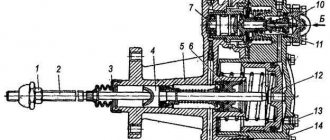
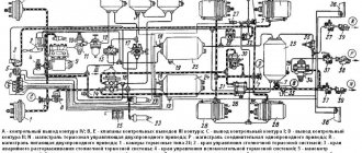
Fig.1. Pneumatic-hydraulic amplifier (PGU) of the clutch control drive KamAZ-4310, 55111, 43118, 5320 1.3 - spring washers; 2, 4, 23 — bolts; 5 — air supply cover; 6 — adjusting gasket; 7 — valve assembly; 8 — rod nut; 9,11, 19. 44 — washers; 10 - cone; 12, 22— saddles; 13, 27, 46 — springs; 14 — tube; 15—rod; 16 —PSU assembled; 17 — PGU diaphragm assembly; 18, 53 — nuts; 20 - diaphragm; 21 — saddle tab; 24 — front housing plug; 25—front CCGT housing; 26, 32, 35, 41, 42— sealing rings; 28, 34 — cuffs; 29, 33, 59 — pistons; 30—ring; 31 — body; 36 — bushing; 37 — thrust bushing; 38 — spacer spring; 39, 61 — spacer sleeve; 40, 60 — assembled cuffs; 43 — seal housing; 45, 62 — thrust rings; 47 — cap; 48 - valve; 49 — breather with valve assembly; 50 — retaining ring; 51— protective cover; 52 — piston pusher; 54 — spherical nut; 55 — rear housing; 56 - jet; 57 - ball; 58 - saddle Technical conditions for defect detection and repair of parts of PGU KamAZ-4310, 55111, 43118, 5320 with a hydraulic clutch drive Rear housing of PGU KamAZ-4310, 55111, 43118, 5320. Traces of corrosion, scuffing, nicks on the working surface of the body are not allowed. diameter more than 28.06 mm. The front body of the PGU KamAZ-4310, 55111, 43118, 5320. The following are not allowed: - scuffs, dents, nicks in the working surface A of the body; — diameter A more than 90.2 mm. Cuffs and O-rings. The following is not allowed: - wear and swelling of cuffs and sealing rings; — ruptures and cracks of working edges. Outlet seal. Signs of aging (cracks, breaks, loss of elasticity) are not allowed. Membrane. Tears, cracks, and loss of elasticity are not allowed. The body of the follower piston PGU Kamaz-4310, 55111, 43118, 5320. The following are not allowed: - nicks, scuffs, dents on the working surface - the diameter of the working surface is more than 28.06 mm. Assembling the PGU Kamaz-4310, 55111, 43118, 5320 - Install the cuff 28 on the pneumatic piston 29 (see Fig. 1) - Apply lubricant to the groove of the piston 29 - Install the o-ring 26 and the pneumatic piston 29 assembly into the front housing 25 - Install into the seal housing 43, ring 42 - Place seal rings 41 and 42 onto housing 43 - Install cuff 60, spacer sleeve 61, thrust ring 62, thrust sleeve 37, spacer spring 38, spacer sleeve 39, spacer sleeve 40, housing on clutch release piston 59 43 piston seal assembly with o-rings 41 and 42 and washer 44 of the seal housing - Place o-ring 32 and cuff 34 on follower piston 33 - Insert follower piston 33 assembled into housing 31 - Install follower piston 31 of KamAZ-4310 PGU into housing 31, 55111, 43118, 5320 thrust ring 30 — Place the o-ring 35 on the body 31 — Install the membrane tab 21, one washer 19, two membranes 20, then another washer 19 on the seat 22 — Screw in the nut 18 securing the membrane — Lock the nut 18 by pressing the edge nuts into the groove at one point - Place washer AND small on the amplifier valve stem 15, cone 10, large washer 9, valve stem tube 14, spring 13, valve seat 12, small washer 11, cone 10, large washer 9, tighten nut 8 — Install the retaining ring 50 into the rear housing 55 of the amplifier — Install the rear housing 55 in a vice — Screw in the breather 49 — Install and screw the bypass valve 48 assembled with cap 47 — Install the spring 46 of the pneumatic piston — Install into the front housing of the PGU KamAZ-4310, 55111 , 43118, 5320 spring 27 and membrane 17 of the amplifier gear assembly, aligning the holes of the membrane with the holes in the front housing of the amplifier - Install the front housing 25 of the amplifier onto the rear housing of the amplifier, screw in bolts 2 and 23 fastenings with spring washers 1 - Install gaskets 6 and valve 7 amplifier assembly into the front amplifier housing 25. When installing the valve, it is necessary to use gaskets 6 to adjust the size of the initial gap (2+0.5 mm) between the gearbox valve and the diaphragm seat. There must be at least one gasket. — Install the air supply cover 5 on the front housing 25 of the amplifier, aligning the holes, and screw in the fastening bolts 4 with spring washers 3 — Remove the pneumatic booster assembly from the vice — Check the Kamaz-4310, 55111, 43118, 5320 PGU for leaks and operability. When pump 10 is operating, it is necessary to unscrew the bypass valve half a turn for 3-4 seconds. In this case, the air in the hydraulic system will be released through pipeline 12 into tank 11. After all the air has come out, close the bypass valve. At the same time, using pump 10 and a tap, the control cylinder is filled with brake fluid. Check the tightness of the amplifier hydraulic system using control cylinder 7. In this case, valve 15 of the pneumatic system must be closed (there should be no air pressure in the pneumatic system). Checking the tightness of the pneumatic system of the PSU Kamaz-4310, 55111, 43118, 5320 is carried out using a compressed air tank 5. During the test, tank 5 must be under an air pressure of 687 kPa (7 kgf/cm2) with valve 3 closed. With valve 15 open, air leakage through the amplifier gearbox is unacceptable. In this case, the air pressure in tank 5, controlled by a 4% pressure gauge, should not decrease during the 1 minute acceptance test.
Repair of the clutch master cylinder KamAZ-4310, 55111, 43118, 5320 Dismantling the clutch master cylinder KamAZ-4310, 55111, 43118, 5320 - Remove the protective cover 2 (Fig. 2) from the cylinder body 3 together with the pusher 1 - Install the master cylinder in a vice , clamping the body 3. Unscrew the plug 8, remove the gasket 7, spring b. Using piston pusher 1, push piston 4 with cuff 5 out of body 3 - Wash and blow all parts with compressed air. Technical conditions for the repair of parts of the clutch master cylinder KamAZ-4310, 55111, 43118, 5320. The following is not allowed: - the diameter of the master cylinder body is more than 28.06 mm; — scuff marks on the working surface of the piston master cylinder housing are less than 27.92 mm; - wear and swelling of the cuff. Fig.2. Clutch master cylinder KamAZ-4310, 55111, 43118, 5320 1 — piston pusher assembly; 2 — protective cover; 3 — clutch master cylinder housing; 4 — piston; 5 - cuff; 6 - spring; 7 - gasket; 8 - plug; 9 — main cylinder assembly Assembly of the clutch master cylinder KamAZ-4310, 55111, 43118, 5320 — Install piston 4, cuff 5, spring 6 into the body 3 (see Fig. 2) of the master cylinder and screw in plug 8 with gasket 7. — Install the protective cover 2 on the pusher 1 with the sealing ring, insert the pusher into the body 3 and connect the cover to the body
_______________________________________________________________________________
_______________________________________________________________________________
_______________________________________________________________________________
- Clutch KamAZ-5320 and its components
- Repair of PGU and Kamaz clutch master cylinder
- Gearbox gearbox KamAZ 141
- Gearbox gearbox KamAZ ZF 16
- Gearbox 152 Kamaz with divider
- Gearbox gearbox 154 Kamaz
- Gearbox Kamaz-4308
- Clutch of a Kamaz-4308 car
- Clutch and gearbox KamAZ-65115
- Disassembly and assembly of Kamaz-4310, 55111, 43118 gearboxes
_______________________________________________________________________________
- Cylinder block, head and valves Kamaz-740
- Fuel system of Kamaz-740 diesel engine
- Adjustments and repairs of fuel injection pump Kamaz-740
- Drive axles of the Kamaz-4310 vehicle
- Repair of Kamaz drive axle gearbox
- Rear axle KamAZ-4308
- Axles and suspensions of Kamaz-65115 dump trucks
- Installation of Kamaz cardan shafts and axles
- Repair of Kamaz vehicle transfer case
- Kamaz power steering - adjustments and repairs
- Repair of Kamaz steering gear parts
- Steering parts Kamaz-4308
- Parts of the brake system Kamaz-4308
- Brake system and brake drive Kamaz
- Repair of brake valves and Kamaz compressor
- Suspension Kamaz-4310, 55111, 43118 and their parts
- Frame and suspension of the Kamaz-4308 car
- Cabin details and platform KamAZ-65115
- Cabin components Kamaz-4308
- Platform mechanism of Kamaz vehicles
- Klintsy KS 65719-5K truck crane based on KamAZ-6522 chassis
- Truck crane KC-35719-7-02 based on Kamaz-43118 chassis
- Truck crane Galichanin KC-55713-1K based on KamAZ-65115 6x4
- Ivanovets KS-45717K-1/1R truck crane based on KamAZ-65115 chassis
- Ivanovets KS-3577-3/4 truck crane on KamAZ-43253 4x2 chassis
What kind of “beast” is this PSU
Let's start with the definition of the abbreviation "PGU" - this is a pneumohydraulic booster, an integral element of the clutch assembly. KAMAZ trucks are very large and massive, so they are not easy to drive. The driver of such a car would become a weightlifter pressing the clutch pedal if such a technological solution as a PSU did not exist. It makes life behind the wheel of a truck easier and more comfortable.
Simply put, it is responsible for reducing the applied force on the pedal. Although the pneumohydraulic booster itself is small in size, it performs a serious task - it facilitates the process of driving a heavy vehicle. Without it, changing gears would be a difficult process. All latest CCGT models consist of:
- tracking systems;
- executive pneumatic cylinder;
- indicator of the degree of wear of the linings on the driven disk.
The pressure of the liquid, which is located in the main cylinder of the device, is transported to the pneumohydraulic booster. This, in turn, forces the hydraulic pistons and servo system to work. When the pressure decreases, everything returns to its original position.
Repair and adjustment of KAMAZ PSU | TRUCK.BIZ
Do you want to know how to recognize the source of the breakdown and repair the KAMAZ PSU yourself? Then you have come to the right place; in this article we will walk you through this process step by step.
What kind of “beast” is this PSU
Let's start with the definition of the abbreviation "PGU" - this is a pneumohydraulic booster, an integral element of the clutch assembly. KAMAZ trucks are very large and massive, so they are not easy to drive. The driver of such a car would become a weightlifter pressing the clutch pedal if such a technological solution as a PSU did not exist. It makes life behind the wheel of a truck easier and more comfortable.
Simply put, it is responsible for reducing the applied force on the pedal. Although the pneumohydraulic booster itself is small in size, it performs a serious task - it facilitates the process of driving a heavy vehicle. Without it, changing gears would be a difficult process. All latest CCGT models consist of:
- tracking systems;
- executive pneumatic cylinder;
- indicator of the degree of wear of the linings on the driven disk.
The pressure of the liquid, which is located in the main cylinder of the device, is transported to the pneumohydraulic booster. This, in turn, forces the hydraulic pistons and servo system to work. When the pressure decreases, everything returns to its original position.
Causes of CCGT failure
- If the PSU follower piston is jammed, this is due to swelling of the rubber ring or sealing lip.
- In the case when the compressed air in the pneumatic-hydraulic booster enters in small quantities or does not enter at all, the inlet valve of the CCGT unit will be “to blame”.
- When a “sinking” situation is observed in the operation of the pedal, this means that air has entered the hydraulic drive.
The first signs of problems with the pneumohydraulic booster
For beginners in the repair of KAMAZ CCGT units, it is sometimes difficult to recognize the first signals of a malfunction in the operation of the CCGT unit. But here is a small list of possible errors in clutch operation:
- When starting to move or when changing gear, the device responds late.
- The device responds only with significant amplification.
- Periodic “wedges” of the device.
If at least one of the above symptoms is present, then you urgently need to look for and troubleshoot the pneumatic-hydraulic booster unit.
We begin the repair of KAMAZ CCGT units with our own hands
Having studied all the indicators of breakdown, have you decided to carry out the repair yourself? Then you need to start by disassembling the unit, the cycle of which is carried out strictly in the following order:
- The rear housing of the pneumatic booster is secured in a vice.
- The bolts and washers are unscrewed one by one.
- The air supply cover is removed.
- The valve is pulled out from the CCGT housing.
- The front housing assembly with the pneumatic piston is removed.
- The springs are removed from the membrane and pneumatic piston.
- The diaphragm is removed.
- The seal housing, thrust ring, follower piston and clutch release piston assembly are pulled out from the rear housing.
- The cap with the outlet seal and the bypass valve are unscrewed.
- The previously secured rear housing is released from the vice.
- The retaining ring is pulled out.
- The cones, washers and seat are removed from the valve stem.
- The sealing ring is removed from the follower piston body.
- The follower piston is removed and the remaining parts are removed from it.
- The O-ring and pneumatic piston are pulled out from the front housing.
- The cuff is removed from the pneumatic piston.
- All removed elements are cleaned in petroleum product: kerosene or gasoline, blown with compressed air and subjected to troubleshooting.
- After a high-quality inspection of the parts and repair of the required spare parts or their replacement, assembly is carried out in the reverse order.
How can you adjust a KAMAZ CCGT unit?
The final stage of device restoration is the adjustment of the KAMAZ PGU. To do this, it is necessary to ensure a full stroke of the pneumatic amplifier pusher of at least 25 mm . Because when the indicator is low, the clutch is completely disengaged. Thus, the full stroke of the pusher is tested by pressing the clutch pedal as hard as it will go.
If the stroke is not at the proper level, then the fluid level in the reservoir of the clutch master cylinder and the free stroke are re-tested. If a need is detected, air is removed from the hydraulic system. In order for the CCGT to serve efficiently and reliably, it is important not to forget about its timely repair and maintenance.
Source: https://gruzovik.biz/articles/remont-i-regulirovka-pgu-kamaz
Causes of CCGT failure
- If the PSU follower piston is jammed, this is due to swelling of the rubber ring or sealing lip.
- In the case when the compressed air in the pneumatic-hydraulic booster enters in small quantities or does not enter at all, the inlet valve of the CCGT unit will be “to blame”.
- When a “sinking” situation is observed in the operation of the pedal, this means that air has entered the hydraulic drive.
Reasons for repairing CCGT units
The most common problems with WABCO CCGT units are presented in the following table.
| Malfunction | Possible reasons |
| clutch failure |
|
| requires a lot of force when pressing the clutch pedal |
|
| clutch "falls out" | air has entered the hydraulic drive |
| the clutch does not disengage completely (the pedal “slips” or “drives”) |
|
| fluid leak in master cylinder |
|
The first signs of problems with the pneumohydraulic booster
For beginners in the repair of KAMAZ CCGT units, it is sometimes difficult to recognize the first signals of a malfunction in the operation of the CCGT unit. But here is a small list of possible errors in clutch operation:
- When starting to move or when changing gear, the device responds late.
- The device responds only with significant amplification.
- Periodic “wedges” of the device.
If at least one of the above symptoms is present, then you urgently need to look for and troubleshoot the pneumatic-hydraulic booster unit.
We begin the repair of KAMAZ CCGT units with our own hands
Having studied all the indicators of breakdown, have you decided to carry out the repair yourself? Then you need to start by disassembling the unit, the cycle of which is carried out strictly in the following order:
- The rear housing of the pneumatic booster is secured in a vice.
- The bolts and washers are unscrewed one by one.
- The air supply cover is removed.
- The valve is pulled out from the CCGT housing.
- The front housing assembly with the pneumatic piston is removed.
- The springs are removed from the membrane and pneumatic piston.
- The diaphragm is removed.
- The seal housing, thrust ring, follower piston and clutch release piston assembly are pulled out from the rear housing.
- The cap with the outlet seal and the bypass valve are unscrewed.
- The previously secured rear housing is released from the vice.
- The retaining ring is pulled out.
- The cones, washers and seat are removed from the valve stem.
- The sealing ring is removed from the follower piston body.
- The follower piston is removed and the remaining parts are removed from it.
- The O-ring and pneumatic piston are pulled out from the front housing.
- The cuff is removed from the pneumatic piston.
- All removed elements are cleaned in petroleum product: kerosene or gasoline, blown with compressed air and subjected to troubleshooting.
- After a high-quality inspection of the parts and repair of the required spare parts or their replacement, assembly is carried out in the reverse order.
PGU KAMAZ 5320: device, faults, diagram
_______________________________________________________________________________
Repair of pneumatic hydraulic booster and clutch master cylinder for Kamaz vehicles
Dismantling the pneumatic hydraulic booster (PGU) KamAZ-4310, 55111, 43118, 5320
— Install the PGU in a vice, clamping the rear housing 55 (Fig. 1)
— Unscrew the bolts 4 with washers 3 and remove the air supply cover 5
— Remove valve 7 of the amplifier assembly from the front housing of the air amplifier
— Remove bolts 2 and 23 with washers 1 and remove the front housing 25 assembled with the pneumatic piston 29
— Remove the diaphragm spring 27 and the pneumatic piston spring 46
— Remove the diaphragm 17 PGU Kamaz-4310, 55111, 43118, 5320 assembly
— Unscrew the follower piston 33 with housing 31 from the rear housing 55 of the amplifier
— Remove the thrust ring 45 and the clutch release piston 59 assembly from the rear housing 55 of the amplifier and the seal housing 43
— Unscrew and remove the bypass valve 48 of the rear housing assembled with cap 47
— Unscrew the breather 49 securing the outlet cover, remove the cover and seal of the outlet of the Kamaz-4310, 55111, 43118, 5320 PGU
— Remove the rear housing of the Kamaz clutch pneumatic booster from the vice
— Remove the retaining ring 50 of the rear amplifier housing
— Unscrew nut 8 of valve rod 15
— Remove from the valve stem 15 washer 9 large, cone 10, washer 11 small, valve seat 12, spring 18, tube 14, large washer P, cone 10 and small washer 11 of the valve
— Loosen at one point and unscrew the nut 18 of the gearbox membrane
— Remove from the seat 22 washer 19 membranes 20 and tabs 21
— Remove the sealing ring 35 from the follower piston housing 31
— Remove the thrust ring $0 and the follower piston 33 assembly from the follower piston housing 31
— Remove the sealing ring 32 and the cuff 34 from the piston 33
— Remove from the clutch release piston 59 washer 44, piston seal housing 43 assembled with o-rings 41 and 42, piston seal cuff 40, piston seal sleeve 37, spring 38, spacer sleeve 39, thrust ring 62, sleeve 61 and cuff 60
— Remove the sealing rings 41 and 42 from the housing 43
— Remove the pneumatic piston 29 assembly and the sealing ring 26 from the front housing 25
— Remove the cuff 28 from the pneumatic piston 29
— Wash the parts of the Kamaz-4310, 55111, 43118, 5320 PGU, blow them with compressed air and repair them
Fig.1. Pneumohydraulic amplifier (PGU) of the clutch control drive KamAZ-4310, 55111, 43118, 5320
1.3 — spring washers; 2, 4, 23 — bolts; 5 — air supply cover; 6 — adjusting gasket; 7 — valve assembly; 8 — rod nut; 9,11, 19. 44 — washers; 10 - cone; 12, 22—saddles; 13, 27, 46 — springs; 14 — tube; 15—rod; 16 —PSU assembled; 17 — PGU diaphragm assembly; 18, 53 — nuts; 20 - diaphragm; 21 — saddle tab; 24 — front housing plug; 25—front CCGT housing; 26, 32, 35, 41, 42— sealing rings; 28, 34 — cuffs; 29, 33, 59 — pistons; 30—ring; 31 — body; 36 — bushing; 37 — thrust bushing; 38 — spacer spring; 39, 61 — spacer sleeve; 40, 60 — assembled cuffs; 43 — seal housing; 45, 62 — thrust rings; 47 — cap; 48 - valve; 49 — breather with valve assembly; 50 — retaining ring; 51— protective cover; 52 — piston pusher; 54 — spherical nut; 55 — rear housing; 56 - jet; 57 - ball; 58 - saddle
Technical conditions for defect detection and repair of parts of Kamaz-4310, 55111, 43118, 5320 CCGT units with a hydraulic clutch drive
Rear housing of PGU KamAZ-4310, 55111, 43118, 5320. Traces of corrosion, scuffing, nicks on the working surface of the housing are not allowed, diameter more than 28.06 mm.
Front housing of PGU KamAZ-4310, 55111, 43118, 5320. The following are not allowed:
— scuffs, dents, nicks in the working surface A of the body;
— diameter A more than 90.2 mm.
Cuffs and O-rings. Not allowed:
— wear and swelling of cuffs and sealing rings;
— ruptures and cracks of working edges.
Outlet seal. Signs of aging (cracks, breaks, loss of elasticity) are not allowed.
Membrane. Tears, cracks, and loss of elasticity are not allowed.
Follower piston housing for PGU Kamaz-4310, 55111, 43118, 5320. The following are not allowed:
- nicks, scuffs, dents on the working surface
— the diameter of the working surface is more than 28.06 mm.
Assembly of PSU Kamaz-4310, 55111, 43118, 5320
— Install cuff 28 on pneumatic piston 29 (see Fig. 1)
— Apply lubricant to the piston groove 29
— Install the sealing ring 26 and the pneumatic piston 29 assembly into the front housing 25
— Install ring 42 into seal housing 43
— Place seal rings 41 and 42 on housing 43
— Install on clutch release piston 59 cuff 60, spacer sleeve 61, thrust ring 62, thrust sleeve 37, spacer spring 38, spacer sleeve 39, cuff 40, piston seal housing 43 assembled with o-rings 41 and 42 and seal housing washer 44
— Place o-ring 32 and cuff 34 on follower piston 33
— Insert the follower piston 33 assembly into the housing 31
— Install a thrust ring 30 into the body 31 of the follower piston PGU Kamaz-4310, 55111, 43118, 5320
— Place o-ring 35 on housing 31
-Install 22 membranes, tabs 21, one washer 19, two membranes 20, then another washer 19 onto the seat
— Tighten the nut 18 securing the membrane
— Lock nut 18 by pressing the edge of the nut into the groove at one point
— Place washer I small on the amplifier valve stem 15, cone 10, large washer 9, valve stem tube 14, spring 13, valve seat 12, small washer 11, cone 10, large washer 9, tighten nut 8
— Install the retaining ring 50 into the rear housing 55 of the amplifier
— Place the rear housing 55 in a vice
— Screw in the breather 49
— Install and screw the bypass valve 48 assembled with cap 47
— Install spring 46 of the pneumatic piston
— Install spring 27 and membrane 17 of the amplifier gearbox assembly into the front housing of the PGU KamAZ-4310, 55111, 43118, 5320, aligning the holes in the membrane with the holes in the front housing of the amplifier
— Install the front housing 25 of the amplifier onto the rear housing of the amplifier, screw in bolts 2 and 23 fastenings with spring washers 1
— Install gaskets 6 and valve 7 of the amplifier assembly into the front housing 25 of the amplifier.
When installing the valve, it is necessary to use gaskets 6 to adjust the size of the initial gap (2+0.5 mm) between the gearbox valve and the diaphragm seat. There must be at least one gasket.
— Install the air supply cover 5 on the front housing 25 of the amplifier, aligning the holes, and screw in the fastening bolts 4 with spring washers 3
— Remove the pneumatic booster assembly from the vice
— Check the Kamaz-4310, 55111, 43118, 5320 CCGT units for leaks and operability.
When pump 10 is operating, it is necessary to unscrew the bypass valve half a turn for 3-4 seconds. In this case, the air in the hydraulic system will be released through pipeline 12 into tank 11. After all the air has come out, close the bypass valve.
At the same time, using pump 10 and a tap, the control cylinder is filled with brake fluid. Check the hydraulic system of the amplifier for leaks using test cylinder 7.
In this case, valve 15 of the pneumatic system must be closed (there should be no air pressure in the pneumatic system).
Checking the tightness of the pneumatic system of the PGU Kamaz-4310, 55111, 43118, 5320 is carried out using a compressed air tank 5. During the test, tank 5 must be under air pressure of 687 kPa (7 kgf/cm2) with valve 3 closed.
When tap 15 is open, air leakage through the amplifier gearbox is unacceptable. In this case, the air pressure in tank 5, controlled by a 4% pressure gauge, should not decrease during the 1 minute acceptance test.
Repair of clutch master cylinder KamAZ-4310, 55111, 43118, 5320
Dismantling the clutch master cylinder KamAZ-4310, 55111, 43118, 5320
— Remove the protective cover 2 (Fig. 2) from the cylinder body 3 along with the pusher 1
— Install the main cylinder in a vice, clamping the body 3. Unscrew the plug 8, remove the gasket 7, spring b. Use piston pusher 1 to push piston 4 with cuff 5 out of body 3
— Wash and blow off all parts with compressed air.
Specifications for the repair of parts of the clutch master cylinder KamAZ-4310, 55111, 43118, 5320. The following is not allowed:
— the diameter of the master cylinder body is more than 28.06 mm;
— scuff marks on the working surface of the piston master cylinder housing are less than 27.92 mm;
- wear and swelling of the cuff.
Fig.2. Clutch master cylinder KamAZ-4310, 55111, 43118, 5320
1 — piston pusher assembly; 2 — protective cover; 3 — clutch master cylinder housing; 4 — piston; 5 - cuff; 6 - spring; 7 - gasket; 8 - plug; 9 — main cylinder assembly
Assembly of the clutch master cylinder KamAZ-4310, 55111, 43118, 5320
— Install piston 4, cuff 5, spring 6 into housing 3 (see Fig. 2) of the main cylinder and screw in plug 8 with gasket 7.
— Install the protective cover 2 on the pusher 1 with the sealing ring, insert the pusher into the body 3 and connect the cover to the body
_______________________________________________________________________________
_______________________________________________________________________________
_______________________________________________________________________________
_______________________________________________________________________________
How can you adjust a KAMAZ CCGT unit?
The final stage of device restoration is the adjustment of the KAMAZ PGU. To do this, it is necessary to ensure a full stroke of the pneumatic amplifier pusher of at least 25 mm . Because when the indicator is low, the clutch is completely disengaged. Thus, the full stroke of the pusher is tested by pressing the clutch pedal as hard as it will go.
If the stroke is not at the proper level, then the fluid level in the reservoir of the clutch master cylinder and the free stroke are re-tested. If a need is detected, air is removed from the hydraulic system. In order for the CCGT to serve efficiently and reliably, it is important not to forget about its timely repair and maintenance.
Malfunctions of MAZ PGU
Before we begin repairing the unit, we will consider the reasons for its breakdown, as well as possible malfunctions.
The PSU, and then the MAZ clutch booster, fail because:
- Over time, almost every o-ring swells and the surface of the part becomes thinner;
- The clutch drive is not adjusted correctly;
- The cuffs and other elements of the repair kit have worn out in the working cylinder;
- The release fork bends and its bushing wears out.
Due to the breakage of the sealing rings, bypass occurs, a kind of “hissing”, and then leakage of the working fluid.
If you do not repair the MAZ PGU on time, problems will arise with the MAZ clutch booster over time.
Bleeding and adjustment of PGU and GUR on KamAZ trucks
KamAZ PGU is a device designed to reduce the level of pressure exerted by the driver on the clutch pedal.
PGU - hydraulic power steering of a KamAZ pneumatic clutch type.
Design and principle of operation
The PGU device includes:
- spherical type nut;
- lock nut;
- a piston pusher that deactivates the clutch system;
- a cover that protects against damage;
- piston;
- complex type seal;
- bypass and inlet valve;
- cork;
- fuel fluid supply;
- system for compressing air flow.
The diagram also includes the following elements:
- spring mechanism;
- gearbox;
- diaphragm seats.
The operating principle of the PSU is as follows:
- The driver presses the clutch pedal.
- Under the pressure of the fuel fluid, the rod and piston part of the mechanism are activated.
- Movement occurs until the intake valve opens.
- The air flow moves in the direction of the pneumatic piston.
- The fork is retracted and the clutch system is disengaged.
Bleeding and adjustment
In order to adjust the CCGT, it is necessary:
- Adjust the pedal free play. Lower the pedal until the master cylinder starts to operate. After this, debugging is done using an eccentric finger. The gap between the piston part and the pusher should not exceed 1.2 cm. At the end of the procedure, you need to tighten the castle-type nut tightly.
- Adjust the clutch free play. Move the fork handle, remove the spring mechanism and perform debugging.
Procedure for pumping:
- Clean the rubber protective cap of the bypass valve.
- Place a rubber hose onto the valve.
- Place one end into a glass container with working fluid.
- Press the pedal jerkily 3 times, and the fourth time, while holding the pedal, loosen the bypass valve.
- As soon as the release of air bubbles from the liquid stops, you need to close the bypass valve and remove the hose.
Disassembly and repair
Repair of a CCGT unit involves its disassembly. To disassemble the mechanism with your own hands, you need to:
- Place the pneumatic power steering in a vice and clamp the rear housing.
- Unscrew the bolts and remove the air supply cover.
- Remove the amplifier valve from the front housing.
- Remove the spring and diaphragm.
- Pull out the thrust ring and piston part.
- Unscrew the mounting breather and remove the cover from the seal.
- Pull out the retaining ring.
- Remove the seats and washer.
- Remove the cuff.
- Installation and assembly of the KamAZ PGU is performed in the reverse order.
PGU
PGU - hydraulic power steering of a KamAZ pneumatic clutch type. The basic mechanism consists of two cylinders (hydraulic and pneumatic), a piston, a spring with a rod, a follower mechanism, a pusher and an inlet/outlet valve.
As a result of the operation of the mechanism, caused by the action of compressed air and liquid on the pusher, the required force on the pedal during gear shifting is reduced.
Setting up the PSU allows you not only to eliminate malfunctions, but also to adjust the mechanism for maximum comfort for a particular driver. Knowing the structure and operating principle of the PSU, you can easily repair the mechanism yourself.
Design and principle of operation
The PGU device includes:
- spherical type nut;
- lock nut;
- a piston pusher that deactivates the clutch system;
- a cover that protects against damage;
- piston;
- complex type seal;
- bypass and inlet valve;
- cork;
- fuel fluid supply;
- system for compressing air flow.
The diagram also includes the following elements:
- spring mechanism;
- gearbox;
- diaphragm seats.
The operating principle of the PSU is as follows:
- The driver presses the clutch pedal.
- Under the pressure of the fuel fluid, the rod and piston part of the mechanism are activated.
- Movement occurs until the intake valve opens.
- The air flow moves in the direction of the pneumatic piston.
- The fork is retracted and the clutch system is disengaged.
Bleeding and adjustment
In order to adjust the CCGT, it is necessary:
- Adjust the pedal free play. Lower the pedal until the master cylinder starts to operate. After this, debugging is done using an eccentric finger. The gap between the piston part and the pusher should not exceed 1.2 cm. At the end of the procedure, you need to tighten the castle-type nut tightly.
- Adjust the clutch free play. Move the fork handle, remove the spring mechanism and perform debugging.
Procedure for pumping:
- Clean the rubber protective cap of the bypass valve.
- Place a rubber hose onto the valve.
- Place one end into a glass container with working fluid.
- Press the pedal jerkily 3 times, and the fourth time, while holding the pedal, loosen the bypass valve.
- As soon as the release of air bubbles from the liquid stops, you need to close the bypass valve and remove the hose.
Disassembly and repair
Repair of a CCGT unit involves its disassembly. To disassemble the mechanism with your own hands, you need to:
- Place the pneumatic power steering in a vice and clamp the rear housing.
- Unscrew the bolts and remove the air supply cover.
- Remove the amplifier valve from the front housing.
- Remove the spring and diaphragm.
- Pull out the thrust ring and piston part.
- Unscrew the mounting breather and remove the cover from the seal.
- Pull out the retaining ring.
- Remove the seats and washer.
- Remove the cuff.
- Installation and assembly of the KamAZ PGU is performed in the reverse order.
Possible malfunctions of the PSU:
- The drive is jammed. In this case, it is recommended to flush all hydraulic system elements and change the oil.
- The clutch is lagging. Use higher quality fuel fluid (for example, meeting Euro-5 standards). If this does not help, replace the piston seal.
- The clutch hisses and there is no boost. Inspect the intake valve and replace if necessary. It is also recommended to inspect the cuffs and the follower piston ring.
KamAZ PGU: Design and principle of operation
The applied forces required for the truck's operating processes are proportional to the dimensions of the vehicle. KamAZ PGU reduces the load required for the functioning of the most important element in driving a vehicle, the clutch.
An uninitiated user is unlikely to appreciate the unit, because without an amplifier, the gear shift circuit and the operating condition of the car will not be affected. However, the direct participant in management knows the true price of the mechanism. With the absence of a PSU, driver fatigue increases and the maneuverability of the equipment decreases. As a result, road safety suffers and the number of accidents increases, which means human lives.
KamAZ-5320, PGU: design and principle of operation
Cars October 17, 2017
What is the KamAZ-5320 PGU device? This question interests many beginners. This abbreviation may confuse an ignorant person. In fact, the PGU is a pneumatic hydraulic power steering. Let's look at the features of this device, its operating principle and types of maintenance, including repairs.
- 1 – spherical nut with lock nut.
- 2 – piston pusher of the clutch deactivator.
- 3 – protective cover.
- 4 – clutch release piston.
- 5 – back part of the frame.
- 6 – complex seal.
- 7 – follower piston.
- 8 – bypass valve with cap.
- 9 – diaphragm.
- 10 – inlet valve.
- 11 – graduation analogue.
- 12 – pneumatic type piston.
- 13 – drain plug (for condensate).
- 14 – front part of the body.
- “A” – supply of working fluid.
- “B” – supply of compressed air.
Purpose and device
A truck is a fairly massive and large-sized vehicle. Controlling it requires remarkable physical strength and endurance. The KamAZ-5320 PGU device makes it easier to adjust the vehicle. This is a small but useful device. It makes it possible not only to simplify the driver’s work, but also increases work productivity.
Design and features of KamAZ PSU
Most KamAZ vehicles, both old and recent, use a power amplifier in their transmission design, based on the principles of pneumatics and hydraulics. The unit is installed on KamAZ vehicles: 4310, 55111, 65115, etc. The application is determined by the force developed by the springs to operate the clutch with such a large weight. The average person is not able to operate a KamAZ vehicle without an amplifier during the working day without losing vigilance and attention. The operation of the KamAZ PGU makes it easier to complete the task; the product is built into the clutch mechanism, due to which the driver’s fatigue and performance remain at the required level.
A feature of some KamAZ vehicles is the simultaneous use of a PSU with a gearbox divider. As a rule, the amplifier is an integral part of the box, located between the box and the divider. Switching speeds is accompanied by turning off the divider; the pneumatics of the machine are responsible for this. The process is possible thanks to the valve, which is actuated by the PSU rod. This means that the divider operates and disengages synchronously, by applying and releasing pressure from the foot clutch lever.
Repairing MAZ PGU - photo, instructions
Read below about how to upgrade the PSU for MAZ.
When repairing a part, it must be removed from the vehicle.
On KAMAZ the PGU is installed on the right, on MAZ - on the left along the route.
Then we take the key 14, unscrew the fitting of the hose, tube (here is the working fluid).
Using a 17 key, remove the PSU by unscrewing 2 screws.
We take a 13 key, unscrew the air supply screws, dismantle them, unscrew the inlet and outlet valves.
Using a hexagon, unscrew the screws, disconnect the housing of the MAZ 4370 PGU, remove the piston, and carefully unscrew the breather.
We also dismantle the bypass valve, o-rings, piston seals, and retaining ring.
Carefully remove the MAZ clutch release piston, piston seal housing, cuff.
We hammer in a small plug instead of the rod sealing piston in the MAZ clutch booster. We screw the grease nipple in place of the MAZ bypass valve.
Squeeze out the piston. After you bleed the PSU on the MAZ, wash all parts of the air-hydraulic booster in kerosene or gasoline. If some elements are worn out, we replace them with new ones (cuffs, rings).
We install a cuff on the piston, replace the cuff in the ring of the seal housing. We install a new one on the clutch release piston. This is the only way that malfunctions will not appear at the MAZ CCGT over time.
We install the membrane and assemble the PSU. The valve block and air supply cover are installed last.
We attach the pneumatic hydraulic booster to the car, add fluid to the hydraulic drive and pump it up.
How to pump up a PGU on a MAZ - instructions
The problem is not solved? Repair the CCGT for MAZ.
When replacing a part, do not forget to check the stroke rod:
- Move the rod away from the lever;
- Carefully push it aside;
- Turn the MAZ clutch lever from the MAZ 4370 PGU;
- Measure the distance to the beginning of the lever.
The distance should be more than five cm. If the indicator is less than fifty mm, we recommend repairing the MAZ CCGT unit further:
- We remove the lever from the MAZ shaft, attach the MAZ pneumatic hydraulic clutch one spline closer to the body;
- Carefully install the PSU rod into the drive lever.
If you notice other malfunctions in the MAZ PSU, we recommend replacing the repair kit. If the problem cannot be solved, you can always find new spare parts at the lowest prices in our catalog.
Operating principle of CCGT
Today, force converters of several types are built into vehicle transmissions, however, the operating principle of the KamAZ PGU is the same. Structurally, the mechanism is connected by two nodes placed in the frame:
- Tracking mechanism;
- A cylindrical chamber that performs functions using pneumatics.
The tracking device controls the PSU by monitoring the force with which the driver presses the foot clutch lever. When the pressure reaches the desired value, a portion of the air mass is supplied to the cylinder. The tracking device includes a membrane, which sometimes acts as a seal for the frame parts. The mechanism also includes a piston connected to the foot clutch lever via hydraulics. In addition, there are intake and exhaust valves, both of which are pneumatic and interact with the piston. Since both hydraulic and pneumatic elements are involved in the operation of the mechanism, both air and liquid are supplied to the CCGT unit.
KamAZ-5320, PGU: design and principle of operation
What is the KamAZ-5320 PGU device? This question interests many beginners. This abbreviation may confuse an ignorant person. In fact, the PGU is a pneumatic hydraulic power steering. Let's look at the features of this device, its operating principle and types of maintenance, including repairs.
- 1 – spherical nut with lock nut.
- 2 – piston pusher of the clutch deactivator.
- 3 – protective cover.
- 4 – clutch release piston.
- 5 – back part of the frame.
- 6 – complex seal.
- 7 – follower piston.
- 8 – bypass valve with cap.
- 9 – diaphragm.
- 10 – inlet valve.
- 11 – graduation analogue.
- 12 – pneumatic type piston.
- 13 – drain plug (for condensate).
- 14 – front part of the body.
- “A” – supply of working fluid.
- “B” – supply of compressed air.
A truck is a fairly massive and large-sized vehicle. Controlling it requires remarkable physical strength and endurance. The KamAZ-5320 PGU device makes it easier to adjust the vehicle. This is a small but useful device. It makes it possible not only to simplify the driver’s work, but also increases work productivity.
The node in question consists of the following elements:
- Piston pusher and adjusting nut.
- Pneumatic and hydraulic piston.
- Spring mechanism, gearbox with cover and valve.
- Diaphragm seats, control screw.
- Bypass valve and piston follower.
Peculiarities
The amplifier housing system consists of two elements. The front part is made of aluminum, and the rear part is made of cast iron.
A special gasket is provided between the parts, which acts as a seal and diaphragm. The follower mechanism automatically regulates the change in air pressure on the pneumatic piston.
This device also includes a sealing collar, springs with diaphragms, as well as inlet and outlet valves.
Operating principle
When the clutch pedal is pressed under fluid pressure, the KamAZ-5320 PGU device presses on the rod and piston of the follower, after which the structure, together with the diaphragm, moves until the intake valve opens. The air mixture from the vehicle's pneumatic system is then supplied to the pneumatic piston. As a result, the forces of both elements are summed up, which allows you to retract the fork and disengage the clutch.
After the foot is removed from the clutch pedal, the pressure of the supply main fluid drops to zero. As a result, the load on the hydraulic pistons of the actuator and follower mechanism is reduced.
For this reason, the hydraulic piston begins to move in the opposite direction, closing the inlet valve and blocking the flow of pressure from the receiver. The pressure spring, acting on the follower piston, moves it to its original position.
Amplifiers used on KamAZ
Structurally, KamAZ vehicles provide for the use of products of both domestic and foreign production. The operating principle of the mechanisms is identical; the devices differ in characteristics and design.
- Thus, the 5320 amplifier, produced at the Kama plant, structurally uses a vertical arrangement of the follower mechanism; the pneumatic cylinder is also installed vertically. Such devices are used on modifications: 5320, 4310, 43118, etc.
- The WABCO amplifier is manufactured in the United States of America. The product is distinguished by its compact size and lining wear indicators, which facilitates the use of the PGU. Similar devices are used on new KamAZ vehicle models: 5460, 6450, 6460, 65117, etc. The amplifier is compatible with “154” series gearboxes, which are used with power units that meet Euro-2 and Euro-3 standards.
- PGU "WABCO" for KamAZ modifications: 6460, 6520 and other equipment with ZF gearboxes.
- PGU "WABCO" for modifications of KamAZ: 4308, on which a ZF five-speed gearbox is installed.
- CCGT units made according to the “WABCO” type are produced in Ukraine and Turkey.
PSU for KamAZ 5320:
How to pump up a PSU on a KAMAZ Euro
Russian special equipment is not easy to operate. The large Kamaz truck is a large, clumsy vehicle. However, modern designers rely on modernizing existing equipment, so heavy-duty vehicles are equipped with new, technically more advanced mechanisms.
One of such mechanisms is considered to be PGU. This abbreviation means pneumohydraulic booster. The system is closely related to the operation of the power steering. PGU is a pneumohydraulic booster that helps the driver depress the clutch pedal more easily. Together with the hydraulic booster, the mechanism facilitates the moment of gear shifting.
There are many modifications of the Kamaz vehicle, because today it is the most popular domestic truck. High load capacity, durability of mechanisms, ease of operation, repair, and searching for parts have made the car a truly popular brand. That is why well-proven models have survived from the last century to the present day. However, progress strives forward as always. Foreign competitors produce many more structurally advanced vehicles, forcing Kamaz to switch to the Euro format engine system.
Malfunctions of KamAZ PGU
Inspection and testing of the performance of the GPU is carried out together with the clutch mechanism. The procedure for carrying out manipulations is described in the documentation for each car. The amplifier is checked for oil and air leaks, and the tightening forces of the fasteners are monitored. Adjust the stroke of the foot lever by positioning the spherical nut, and check the fluid level in the hydraulic tank. In case of serious breakdowns, the KamAZ PSU is replaced or repaired.
The replacement is accompanied by manipulations:
- Open the bypass valve to allow air masses to escape;
- Remove the spring mechanism pressing the clutch deactivation fork shaft lever;
- Remove lubricant from the hydraulic circuit;
- Disconnect the pneumatic and hydraulic pipes;
- Remove the PSU.
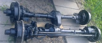
Dismantled KamAZ PSU:
After dismantling, the technical condition of the CCGT parts and assemblies is checked. Attention is paid to the seals and the cylinder mirror - a surface without traces of mechanical impact. In addition, the internal diameter is measured to ensure compliance with established tolerances and fits.
A repaired or newly purchased amplifier is mounted in place by performing the steps in reverse order. After installation, check the tightness of the hydraulics and pneumatics. To do this, fill the circuit with liquid in the required volume.
As a rule, the amplifier works without problems for five to ten years. In case of breakdowns, it is more advisable to replace the product with a new one. CCGT units are repaired for minor or non-serious defects. The reasons for the failure of the KamAZ CCGT unit, possible malfunctions and their elimination are carried out on the equipment by service workers.
Frequently observed breakdowns:
- Under the influence of oil, the rubber seals swelled, and as a result, the PGU piston jammed;
- The exhaust valve does not allow air masses to pass through, or does not allow air masses to pass through in an insufficient volume;
- The presence of air bubbles in the hydraulic circuit, as a result, failures in the operation of the foot lever.
Repair of clutch parts
Defects in clutch parts and their elimination.
The clutch may have the following defects: slipping and incomplete disengagement of the discs, wear of the linings and the discs themselves, warping of the pressure plate, risks and cracks on it, loose fastenings, loss of elasticity of the springs, wear of the pedal axle bushings, etc.
Ferodo disk burst
Repair of clutch parts consists of replacing faulty parts with new ones, straightening them and welding cracks. If the thickness of the pressure plate is less than the nominal value, in addition to thermal insulating washers, metal spacers can be installed under the springs.
When replacing worn friction linings, they are riveted to the disk so that the heads of the rivets are buried in the linings by at least 1-1.5 mm. The driven disk with new linings is checked for runout using the transmission drive shaft as a mandrel.
Output from intermediate
Discs that have circular marks and burrs are leveled on a surface grinder, sometimes with preliminary turning on a lathe. If there is significant warping or cracks, the discs are replaced with new ones. The worn surfaces of the switch levers are fused with steel using gas or electric welding, and then processed according to a template and hardened.
Do-it-yourself KamAZ PSU repair
If you perform the work yourself, the manipulations are carried out according to the instructions. First, disassemble the dismantled device in this order:
- Fix the back of the frame using a clamp;
- Unscrew the fasteners;
- The closing element supplying air masses is dismantled;
- The valve is removed;
- The frame is dismantled together with the pneumatic circuit piston;
- The spring elements of the diaphragm and piston of the pneumatic circuit are removed;
- The membrane is dismantled;
- They sort out: seal, thrust damper, tracking and clutch deactivation pistons;
- The closing element with the outlet gasket and bypass valve is dismantled;
- The back of the frame is removed from the holder;
- The retaining ring is removed;
- The valve stem is disassembled;
- The seal ring of the tracking piston housing is removed;
- The tracking piston is disassembled;
- You get the o-ring and pneumatic piston;
- The cuff is removed from the pneumatic piston.
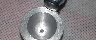
Self-repair of CCGT:
After the CCGT unit has been sorted out at KamAZ, the parts are cleaned, dried and inspected for damage. Rejected parts are replaced with new ones and the product is assembled in the opposite order.
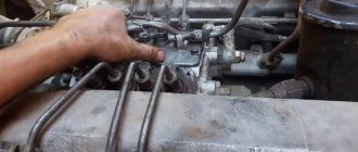
Adjustment of KamAZ PGU:
TRUCKS GAZ, ZIL, KAMAZ, URAL, MAZ, KRAZ
_________________________________________________________________________________________
Replacement and repair of PGU and Kamaz clutch master cylinder
Disassembling the pneumatic hydraulic booster (PGU) KamAZ-4310, 55111, 43118, 5320 - Install the PGU in a vice, clamping the rear housing 55 (Fig. 1) - Unscrew the bolts 4 with washers 3 and remove the air supply cover 5 - Remove the valve 7 of the amplifier assembly from front casing of the pneumatic booster - Unscrew bolts 2 and 23 with washers 1 and remove the front casing 25 assembled with the pneumatic piston 29 - Remove the membrane spring 27 and the pneumatic piston spring 46 - Remove the diaphragm 17 of the Kamaz-4310, 55111, 43118, 5320 PGU assembly - Unscrew the follower piston 33 with housing 31 from the rear housing 55 of the amplifier - Remove the thrust ring 45 and the clutch release piston 59 assembly from the rear housing 55 of the amplifier and the seal housing 43 - Unscrew and remove the bypass valve 48 of the rear housing assembly with cap 47 - Unscrew the breather 49 fastening the exhaust hole cover, remove the cover and seal of the outlet hole of the PGU Kamaz-4310, 55111, 43118, 5320 - Remove the rear housing of the Kamaz clutch pneumatic booster from the vice - Remove the retaining ring 50 of the rear amplifier housing - Unscrew the nut 8 of the valve rod 15 - Remove from the rod 15 valve washer 9 large, cone 10, washer 11 small, valve seat 12, spring 18, tube 14, large washer P, cone 10 and small washer 11 of the valve - Unlock at one point and unscrew the nut 18 of the gearbox membrane - Remove from the seat 22 washer 19 membranes 20 I tabs 21 - Remove the sealing ring 35 from the body 31 of the follower piston - Remove the thrust ring $0 from the body 31 of the follower piston and the follower piston 33 assembly - Remove the o-ring 32 and cuff 34 from the piston 33 - Remove the shutdown piston 59 clutch washer 44, housing 43, piston seal assembly with o-rings 41 and 42, piston seal cuff 40, piston seal sleeve 37, spring 38, spacer sleeve 39, thrust ring 62, sleeve 61 and cuff 60 - Remove the o-rings from the body 43 41 and 42 - Remove from the front housing 25 the pneumatic piston 29 assembly and the sealing ring 26 - Remove the cuff 28 from the pneumatic piston 29 - Wash the parts of the Kamaz-4310, 55111, 43118, 5320 PGU, blow them with compressed air and repair the defects Fig. 1. Pneumatic-hydraulic amplifier (PGU) of the clutch control drive KamAZ-4310, 55111, 43118, 5320 1.3 - spring washers; 2, 4, 23 — bolts; 5 — air supply cover; 6 — adjusting gasket; 7 — valve assembly; 8 — rod nut; 9,11, 19. 44 — washers; 10 - cone; 12, 22— saddles; 13, 27, 46 — springs; 14 — tube; 15—rod; 16 —PSU assembled; 17 — PGU diaphragm assembly; 18, 53 — nuts; 20 - diaphragm; 21 — saddle tab; 24 — front housing plug; 25—front CCGT housing; 26, 32, 35, 41, 42— sealing rings; 28, 34 — cuffs; 29, 33, 59 — pistons; 30—ring; 31 — body; 36 — bushing; 37 — thrust bushing; 38 — spacer spring; 39, 61 — spacer sleeve; 40, 60 — assembled cuffs; 43 — seal housing; 45, 62 — thrust rings; 47 — cap; 48 - valve; 49 — breather with valve assembly; 50 — retaining ring; 51— protective cover; 52 — piston pusher; 54 — spherical nut; 55 — rear housing; 56 - jet; 57 - ball; 58 - saddle Technical conditions for defect detection and repair of parts of PGU KamAZ-4310, 55111, 43118, 5320 with a hydraulic clutch drive Rear housing of PGU KamAZ-4310, 55111, 43118, 5320. Traces of corrosion, scuffing, nicks on the working surface of the body are not allowed. diameter more than 28.06 mm. The front body of the PGU Kamaz-4310, 55111, 43118, 5320. The following are not allowed: - scuffs, dents, nicks in the working surface A of the body; — diameter A is more than 90.2 mm. Cuffs and O-rings. The following is not allowed: - wear and swelling of cuffs and sealing rings; — ruptures and cracks of working edges. Outlet seal. Signs of aging (cracks, breaks, loss of elasticity) are not allowed. Membrane. Tears, cracks, and loss of elasticity are not allowed. The body of the follower piston PGU Kamaz-4310, 55111, 43118, 5320. The following are not allowed: - nicks, scuffs, dents on the working surface - the diameter of the working surface is more than 28.06 mm. Assembling the PGU Kamaz-4310, 55111, 43118, 5320 - Install the cuff 28 on the pneumatic piston 29 (see Fig. 1) - Apply lubricant to the groove of the piston 29 - Install the o-ring 26 and the pneumatic piston 29 assembly into the front housing 25 - Install into the seal housing 43, ring 42 - Place seal rings 41 and 42 onto housing 43 - Install cuff 60, spacer sleeve 61, thrust ring 62, thrust sleeve 37, spacer spring 38, spacer sleeve 39, spacer sleeve 40, housing on clutch release piston 59 43 piston seal assembly with o-rings 41 and 42 and washer 44 of the seal housing - Place o-ring 32 and cuff 34 on follower piston 33 - Insert follower piston 33 assembled into housing 31 - Install follower piston 31 of KamAZ-4310 PGU into housing 31, 55111, 43118, 5320 thrust ring 30 — Place o-ring 35 on the body 31 — Install diaphragms 21, one washer 19, two diaphragms 20, then another washer 19 onto the seat 22 — Screw in nut 18 securing the diaphragm — Lock nut 18 by pressing the edge nuts into the groove at one point - Place washer AND small on the amplifier valve stem 15, cone 10, large washer 9, valve stem tube 14, spring 13, valve seat 12, small washer 11, cone 10, large washer 9, tighten nut 8 — Install the retaining ring 50 into the rear housing 55 of the amplifier — Install the rear housing 55 in a vice — Screw in the breather 49 — Install and screw the bypass valve 48 assembled with cap 47 — Install the spring 46 of the pneumatic piston — Install into the front housing of the PGU KamAZ-4310, 55111 , 43118, 5320 spring 27 and membrane 17 of the amplifier gear assembly, aligning the holes of the membrane with the holes in the front housing of the amplifier - Install the front housing 25 of the amplifier onto the rear housing of the amplifier, screw in bolts 2 and 23 fastenings with spring washers 1 - Install gaskets 6 and valve 7 amplifier assembly into the front amplifier housing 25. When installing the valve, it is necessary to use gaskets 6 to adjust the size of the initial gap (2+0.5 mm) between the gearbox valve and the diaphragm seat. There must be at least one gasket. — Install the air supply cover 5 on the front housing 25 of the amplifier, aligning the holes, and screw in the fastening bolts 4 with spring washers 3 — Remove the pneumatic booster assembly from the vice — Check the Kamaz-4310, 55111, 43118, 5320 PGU for leaks and operability. When pump 10 is operating, it is necessary to unscrew the bypass valve half a turn for 3-4 seconds. In this case, the air in the hydraulic system will be released through pipeline 12 into tank 11. After all the air has come out, close the bypass valve. At the same time, using pump 10 and a tap, the control cylinder is filled with brake fluid. Check the tightness of the amplifier hydraulic system using control cylinder 7. In this case, valve 15 of the pneumatic system must be closed (there should be no air pressure in the pneumatic system). Checking the tightness of the pneumatic system of the PGU Kamaz-4310, 55111, 43118, 5320 is carried out using a compressed air tank 5. During the test, tank 5 must be under an air pressure of 687 kPa (7 kgf/cm2) with valve 3 closed. With valve 15 open, air leakage through the amplifier gearbox is unacceptable. In this case, the air pressure in tank 5, controlled by a 4% pressure gauge, should not decrease during the 1 minute acceptance test.
Repair of the clutch master cylinder KamAZ-4310, 55111, 43118, 5320 Dismantling the clutch master cylinder KamAZ-4310, 55111, 43118, 5320 - Remove the protective cover 2 (Fig. 2) from the cylinder body 3 together with the pusher 1 - Install the master cylinder in a vice , clamping the body 3. Unscrew the plug 8, remove the gasket 7, spring b. Using piston pusher 1, push piston 4 with cuff 5 out of body 3 - Wash and blow all parts with compressed air. Technical conditions for the repair of parts of the clutch master cylinder KamAZ-4310, 55111, 43118, 5320. The following is not allowed: - the diameter of the master cylinder body is more than 28.06 mm; — scuff marks on the working surface of the piston master cylinder housing are less than 27.92 mm; - wear and swelling of the cuff. Fig.2. Clutch master cylinder KamAZ-4310, 55111, 43118, 5320 1 - piston pusher assembly; 2 — protective cover; 3 — clutch master cylinder housing; 4 — piston; 5 - cuff; 6 - spring; 7 - gasket; 8 - plug; 9 — main cylinder assembly Assembly of the clutch master cylinder KamAZ-4310, 55111, 43118, 5320 — Install piston 4, cuff 5, spring 6 into the housing 3 (see Fig. 2) of the master cylinder and screw in plug 8 with gasket 7. — Install the protective cover 2 on the pusher 1 with the sealing ring, insert the pusher into the body 3 and connect the cover to the body
_________________________________________________________________________________________
- GAZ-3307 clutch maintenance
- Steering system GAZ-3307
- Gearbox parts for GAZ-3307
- Maintenance of the rear axle GAZ-3307
- Maintenance of the fuel system of the D-245 diesel engine
- Clutch GAZ-3309 with a diesel engine
- Operations for disassembling the GAZ-3309 gearbox
- GAZ-3309 front axle service
- Repair of cardan shafts of GAZ-3309 cars
_________________________________________________________________________________________
_________________________________________________________________________________________
- Operations for assembling basic components of the ZIL-130 engine
- Service and repair operations for the ZIL-130 gearbox
- Maintenance and repair of ZIL-130 clutch
- Repair and adjustment of the rear axle ZIL-130
_________________________________________________________________________________________
- KAMAZ-4310, 43118, 43114
- KAMAZ-5320, 55111, 53212, 5511, 55102
- KAMAZ-65115, 6520, 65117
- KAMAZ-4308
- Engine KAMAZ-740
_________________________________________________________________________________________
- Parts of the cylinder block and head of the YaMZ-236 engine
- Service maintenance of the YaMZ-236 piston group and crankshaft
- Diagnostics and technical adjustments of the YaMZ-236 engine
- Design and adjustment of fuel injection pump and injectors of the YaMZ-236 engine
- Cylinder block and piston YaMZ-238
- Components of the YaMZ-238 diesel fuel supply system
- Design and adjustment of the fuel injection pump of the YaMZ-238 diesel engine
- Technical design of the YaMZ-239 gearbox
_________________________________________________________________________________________
- Components of the front axle and steering rods of the Maz-5516, 5440
- Steering system of Maz-5516, 5440 cars
- Clutch and gearbox parts Maz-5516, 5440
- Maintenance of drive axles of MAZ-5516, 5440 vehicles
- Power steering for Maz-5551, 5335 cars
- Maintenance of cardan transmission of Maz-5551, 5335 cars
- Maintenance and adjustment of clutch MAZ-5551, 5335
- Repair and service of the rear axle of MAZ-5551, 5335 cars
_________________________________________________________________________________________
- Gearbox Ural-4320
- Construction and adjustment of Ural-4320 bridges
- Maintenance of transfer case Ural-4320
- Steering components Ural-4320
_________________________________________________________________________________________
- Servicing the KRAZ-255, 260 gearbox
- Steering mechanism and power steering Kraz-255, 260
- Adjustments and repairs of the power steering cylinder and steering rods of the Kraz car
- Drive axle components and drive shafts Kraz-255, 260
Adjusting KamAZ PGU
After the mechanism has been rebuilt, repaired, reassembled and put back into place, the final procedure is performed - the amplifier is adjusted. The procedure is considered completed if the pusher of the pneumatic circuit overcomes a distance of at least twenty-five millimeters. A lower value leads to unstable operation and disengagement of the clutch. To test the full stroke, the foot lever is pressed all the way. If the indicator is not at the proper level, check the presence of fluid in the reservoir of the clutch master cylinder and free movement. If air bubbles are detected in the circuit, the masses are removed.
Adjustment
The final stage of returning the system to working capacity is the adjustment of the mechanism. To adjust the unit, it is necessary to ensure the full stroke of the pusher, which is approximately twenty-five millimeters. By pressing the pedal all the way, the clutch performance is measured. A proper indicator indicates that the repair work has been carried out correctly. If the indicator is below the norm of 25, you should first check the presence of hydraulic fluid and the condition of the air systems.
The occurrence of any malfunction of the CCGT is the reason for urgent repairs. Different Kamaz models may have slightly different structure and functionality of the PSU system. The simplest mechanisms are those installed on the 5320, the most popular type of tractor-semi-trailer among the Russian truck industry.