Assembling and adjusting differential bearings
Assemble the differential in the following order:
- Before assembling the differential, lubricate the axle gears, pinions, thrust washers and pinion shafts with transmission oil.
- Install thrust washers onto the journals of the axle gears.
- Install the axle gear and thrust washer assembly into the left gearbox.
- Install the satellites on the axis of the split cross.
- Install the detachable crosspiece (Fig. 168) with satellites in the left satellite box.
Rice.
168. Installing a split crosspiece with satellites in the left gearbox. Install the axle gear with thrust washer assembly in the right gearbox. Holding the axle shaft gear, install the right satellite cup on the left one so that the marks (Fig. 169) (ordinal numbers) of both cups are aligned.
Rice. 169. Installation of satellite boxes according to marks
- Connect the halves with bolts and tighten them. Tightening torque 32-40 N*m (3.2-4.0 kgf*m).
- Install the main drive driven gear onto the gearbox, aligning the bolt holes. Install the bolts and tighten them. Tightening torque 98-137 N*m (10-14 kgf*m).
For the assembled differential, the axle gears must be rotated using a splined mandrel from a force of no more than 59 N (6 kgf) applied over a radius of 80 mm.
Adjust the differential bearings (if they are replaced) in the following order:
- Press the inner rings of the bearings (Fig. 170) of the differential onto the journals of the assembled differential so that there is a gap of 3.5-4.0 mm between the ends of the satellite box and the ends of the inner rings of the bearings.
Rice.
170. Preliminary pressing of the inner rings of the differential bearings Install the differential assembly into the crankcase, then the gasket and crankcase cover and, turning the cover by the casing, roll the bearings so that the rollers take the correct position (Fig. 171). Then use bolts and nuts to evenly connect the cover to the crankcase.
Rice. 171. Rolling differential bearing rollers
Unscrew the bolts again, carefully remove the cover, remove the differential from the crankcase and use a feeler gauge to measure the gaps A and A1 (Fig. 172 and 173) between the ends of the inner rings of the bearings and the gearbox.
Rice. 172. Clearance measurements when adjusting differential bearings
Rice. 173. Gaps A and A1 between the ends of the inner rings of bearings and the satellite box
Source
Engine tightening torques 409
Bolt tightening torque:
- The tightening force of the M8 bolts of the camshaft tires is 1.90 ÷ 2.30 kgf/m;
- Flywheel bolts M10x1.25 with a force of 7.20 ÷ 8.0 kgf/m;
- M8 bolts of the clutch basket with a tension of 2.0 ÷ 2.50 kgf/m;
- Oil seal holder bolts with M6 thread - 0.6 ÷ 0.9 kgf/m;
- Bolt of the upper and middle chain guides with parameters M8x48 - 2.0 ÷ 2.5 kgf/m
Tightening torque for ZMZ 409 engine nuts:
- Connecting rod bolt nuts with M10x1 thread - 6.80 ÷ 7.50 kgf/m
- Exhaust manifold locknuts with M8 thread - 1.9 ÷ 2.3 kgf/m
- Inlet pipe nut with M8x1 thread - 2.9 ÷ 3.6 kgf/m
- Receiver M8 nuts - 2.2 ÷ 2.50 kgf/m
Engine bolt tightening torques:
- Hydraulic tensioner cover bolts with M8x35 thread - 2.0 ÷ 2.5 kgf/m
- M8 bolts for oil sump - 1.2 ÷ 1.8 kgf/m
- Exhaust manifold screen hardware with M6 thread with a tightening torque of 0.35 ÷ 0.5 kgf/m
- M6 bolts of the front and rear cylinder head covers with a force of 1.2 ÷ 1.8 kgf/m
- M10 threaded bolts of the clutch housing amplifier with force - 2.9 ÷ 3.6 kgf/m
| 409 Motor Torque Chart | ||
| List of components and mechanisms | Thread | Tightening torque, kgf m |
| The main tightening torques with mandatory checking of the tightening force: | ||
| Main bearing cap fasteners | M12x1.2 | 10,0 — 11,0 |
| Cardan coupling bolt | M20x1.5 | 17,0 — 20,0 |
| Fastening of camshaft sprockets | M12x1.25 | 5,60 — 6,20 |
| Fastening the intermediate spindle sprockets | M8x60 | 2,50 — 2,70 |
| Additional tightening torques for threaded connections: | ||
| Cranked torsion bar plugs | M8x25 | 3,8…5,2 |
| Chain tensioner fasteners | M8x22 | 2,7…3,0 |
| Clutch housing hardware | M10x1.25x50 | 4,2…5,1 |
| Clutch fork support bolt | M10x1 | 4,2…5,1 |
| Thermal valve fitting | 4…6 | |
| Oil pump drive cover dowel | M8x25 | 2 ÷ 2,5 |
| Thermostat housing fasteners | M8x65 | 2,0…2,5 |
| Chain cover and water pump mountings | M8 | 2,0…2,5 |
| Fastening the cooling pump to the chain cover | M8 | 2,0…2,5 |
| Pump pulley hardware | M8 | 1.9 ÷ 2.3 |
| Valve cover pin | M8 | 0,5…0,7 |
| Hardware for power steering pump bracket | 2,0…2,5 | |
| Fan pulley fastener | M8x16 | 1,4…1,8 |
| Automatic belt tensioner fastening screw | 4,0…5,0 | |
| Hardware for fastening the tension roller to the axle | M8x14 | 1,4…1,8 |
| Coolant Hose Clamps | 0,4…0,6 | |
| Starter fastener | M10x110 | 4,4…5,6 |
| Generator mounting nuts | M8 | 2,0…2,5 |
| Spark plug | 2,1…3,1 | |
| Excitation coil pins | M8 | 0,6…0,9 |
| Knock sensor fastening nut | M8 | 1,5…2,0 |
| Coolant temperature gauge | 1,2…1,8 | |
| Oil pressure gauge | 1,8…3,5 | |
| Throttle pipe mounting screw | Mx55 | 1,2…1,8 |
| Hardware for fastening the fuel line with injectors | 0,6…0,9 | |
| Timing device bolt | M6 | 0,6…0,9 |
| Hardware of the camshaft meter | 0,6…0,9 | |
| Absolute pressure and temperature sensor spindle | 0,6…0,9 | |
| Antifreeze drain plug or tap | 1,8…3,5 | |
| Tightening torques for engine threaded connections with tapered threads: | ||
| K 1/8″ K 1/4″ K 3/8″ | 0,80 — 2,50 (0,78 — 2,45) 2,0 — 5,0 (1,96 — 4,9) 2,0 — 6,0 (1,96 — 5,88) | |
Note:
- 1 kgf m = 9.80665 Nm;
- 1 kgf m = 9.80665 J;
- 1 kgf m = 1 daNm (decanewton meter);
- 1 daNm = 10 Nm.
Healthy ! Camshaft sensor
Designations in the table: 1Tighten the bolts in a specific sequence
2Tighten the hardware according to the diagram *Tighten the dowels in a certain sequence
Healthy ! temperature sensor
Adjustment of clearances and bearings of the drive axle UAZ-3741, UAZ-3962, UAZ-3909, UAZ-2206, UAZ-3303
Adjustment of the gaps in the meshing of gears and in the bearings of the drive axle of UAZ-3741, UAZ-3962, UAZ-3909, UAZ-2206, UAZ-3303 cars is carried out only when replacing gears or bearings, or when axial clearance appears in the driving or driven gears of the main transfers. Replacement of main gears should only be done as a complete set.
Adjusting the bearing of the drive gear of the main gear of the drive axle UAZ-3741, UAZ-3962, UAZ-3909, UAZ-2206, UAZ-3303
Adjustment of the bearing of the drive gear of the main drive of the drive axle must be done by selecting the thickness of the shim pack and tightening the flange nut. The bearing must have such a preload that there is no axial movement of the drive gear and the gear can be rotated by hand without much effort.
Check the bearing preload with a dynamometer. At the same time, disconnect the left half of the crankcase.
Remove the drive gear bearing cap so that cuff friction does not affect the dynamometer readings.
With proper adjustment, at the moment of turning the drive gear by the hole in the flange, the dynamometer should show a force of 1.5-3 kgf for run-in bearings and 2.0-3.5 kgf for new bearings.
When replacing the cover, align the lubrication holes in the crankcase, gasket and cover. The tightening torque of the drive gear flange nut should be 17-21 kgcm.
You cannot even unscrew the nut a little in order to ensure that the cotter pin hole matches the slot in the nut.
If the nut is not tightened sufficiently, the inner rings of the bearing may rotate and, as a result, wear of the adjusting shims and the appearance of dangerous axial play.
If axial play of the drive gear appears during vehicle operation, tighten the flange nut. If the axial play is not eliminated, then reduce the thickness of the shim pack and adjust the bearing as indicated above.
After adjustment, monitor the heating of the bearings while driving. A slight heating of the bearing is not dangerous, but if the neck of the drive axle crankcase heats up to a temperature of 90 degrees or higher, the water on the crankcase boils, this means that the bearing has been overtightened and the overall thickness of the gaskets should be increased.
Adjusting the differential bearings of the drive axle UAZ-3741, UAZ-3962, UAZ-3909, UAZ-2206, UAZ-3303
Adjustment of the differential bearings must be done by selecting the thickness of the package of adjusting shims installed between the ends of the inner rings of both bearings and the gearbox. When replacing main gears and differential bearings, make adjustments in the following sequence:
1. Press the inner rings of the differential bearings onto the journals of the assembled differential so that there is a gap of 3-3.5 mm between the ends of the gearbox and the ends of the inner rings of the bearings.
Remove the axle shafts and install the differential assembly with the driven gear into the crankcase, install the gasket and cover, tighten the cover mounting bolts and, turning the driven gear with a mounting blade through the neck of the crankcase, roll the bearings so that the rollers take the correct position. Then use fasteners to evenly and completely connect the cover to the crankcase.
3. Unscrew the fasteners again. Carefully remove the cover, remove the differential from the axle housing and use a feeler gauge to measure the gaps A and A1 between the ends of the gearbox and the ends of the inner rings of the bearings.
Cylinder head tightening torque
The tightening torque of the M14x1.5 cylinder head bolts of the engine 409051.10 and 409052.10 is tightened in three steps:
- Pre-tightening with a torque of 3.3 ÷ 3.7 kgf/m;
- Then wait one minute or more;
- Tighten the M14x1.5 bolts a third time at an angle of 90 o
The tightening torque for the cylinder head of the propulsion unit 40911.10 with a soft gasket is carried out in three steps:
- The first approach with a force of 6.9 ÷ 8.2 kgf/m;
- Then wait two minutes or more;
- Tighten the third time at an angle of 70o ÷ 75 o
The tightening torque of the 40911.10 engine cylinder head with a rigid gasket is carried out in three steps:
- The first approach with a force of 5.1 kgf/m;
- Then wait one minute or more;
- Tighten the third time at an angle of 90o
The tightening torque of the M14x1.5 bolts (10 pcs) of the cylinder head of the propulsion unit 409.10 is performed in two approaches:
- The first approach with a torque of 4 ÷ 6 kgf/m;
- The second time with a force of 13 ÷ 14.5 kgf/m
The tightening torque for the cylinder head of engine 40906.10 is carried out in three steps:
- Pre-twisting with a torque of 3.3 ÷ 3.7 kgf/m;
- Then wait one minute or more;
- Tighten the third time at an angle of 90o
The tightening torque for the cylinder head of the motor 40904.10 and 40905.10 is made in 3 times:
- Pre-tightening of the cylinder head with a force of 3.3 ÷ 3.7 kgf/m;
- Then wait one minute or more;
- Tighten the third time at an angle of 90o
The tightening torque for the cylinder head of the motor 4213-40, 4213-50 and 4216 is made in 2 times:
- Pre-tightening the stud nut M12x1.25 cylinder head with a force of 8.5 ÷ 9.5 kgf/m;
- Tighten the second time with a torque of 10 ÷ 11 kgf/m.
Tightening torque for cylinder head of motor 4218:
- The tightening torque of the cylinder head stud nut M12x1.25 with a force of 9.0 ÷ 9.4 kgf/m;
Healthy ! Crankshaft sensor
Adjusting the bearings of the final drive of the UAZ Patriot
Axial play in the bearings of the main gear drive gear is not allowed, since if it is present, rapid wear of the gear teeth occurs and the axle may jam.
Check for the presence of axial clearance by rocking the drive gear by the driveshaft mounting flange.
To eliminate the axial play of the drive gear, it is necessary to tighten nut 8 (Figure 1).
At the same time, keep in mind that the nut is cored into the groove of the threaded part of the drive gear and when tightening it will require more force on the wrench.
Tighten the nut carefully until the axial play of the drive gear is eliminated, avoiding overtightening, then tighten the nut.
If it is not possible to tighten the cored nut, then it should first be loosened by 0.5 - 1.0 turns, and then tightened until the axial gap is eliminated and cored.
Axial play in the final drive differential bearings is also not allowed.
Check it by rocking driven gear 2 with crankcase cover 21 removed.
Eliminate the axial play of the driven gear of the main gear by tightening the nut 17 of the differential bearing, having first removed the locking plate 19.
Adjust the main drive bearings in the following order.
1. Select adjusting ring 5 (see Fig. 1). Its thickness d1 (Fig. 2) is determined (with an accuracy of ±0.025 mm) based on the actual dimensions B and D (see Fig. 2 and 3) using the formula d1 = B – (111.960 + G) (mm).
Install the ring into housing 16 (see Fig. 1) of the main gear.
2. Install the drive gear shaft into the front axle housing.
Check the torque of the drive gear shaft. It should be 1.0–2.0 N cm (0.1–0.2 kgf cm).
3. When installing the differential assembly with the driven gear, measure dimension E (Fig. 4), applying an axial force P equal to 4000–5000 N (400–500 kgf), and turning the gear several times so that the bearing rollers take the correct position.
Measure distance B in the crankcase (see Fig. 2) from the axis of the drive gear to the thrust end of the differential bearing.
Based on the actual dimensions B, E and the mounting size of the driven gear, equal to 50 mm, select (with an accuracy of ±0.025 mm) the adjusting ring according to the formula d2 = B – (E + 50 + X) (mm), where d2 is the thickness of the adjusting ring; X - maximum deviation from the mounting dimension, equal to 50 mm, with the corresponding sign (plus or minus), this dimension is applied with an electrograph to the end of the driven gear.
4. Install the differential assembly with the outer rings of its bearings and the adjusting ring into the front axle housing and secure it.
5. Adjust bearings 6 and 22 (see Fig. 1) of the front axle differential by tightening nut 23, periodically rotating the differential so that the bearing rollers take the correct position. After tightening the nut, the total turning torque of the differential drive gear (Mv.w.) must be within Mw. w. + (0.21–0.42) (Nm) . Perform the check by turning the drive gear.
Check and adjust the lateral clearance in the meshing of the gears of the installed new final drive kit after adjusting the position of the gears.
The lateral clearance is checked with an indicator, the stand of which is attached to the axle housing in the direction perpendicular to the surface of the driven gear tooth when the indicator stand is attached to the housing.
Check the gap on three or four teeth evenly spaced around the circumference.
The spread of the gap values should not exceed 0.05 mm.
Normal side clearance should be between 0.15–0.25 mm.
If the side clearance is less than the specified value, then the selected adjusting ring should be replaced with a ring of thinner thickness.
When checking and adjusting the side clearance, it is not necessary to preload the differential bearings.
6. Tighten the adjusting nut 23 until it comes into contact with the bearings and there is no gap in them.
7. Check the engagement of the main gears along the contact patch by painting the teeth of the driven gear with paint (2 teeth in three or four places evenly around the circumference).
8. Braking the drive gear shaft by the flange, rotate the driven gear in both directions until contact marks appear on the gear teeth, as shown in Fig. 5
When adjusting the gear mesh correctly, the contact patch should be located in the places of the teeth shown in the figure (item 1)
When there is contact at the top of the tooth (item 2), move the drive gear towards the driven gear, increasing the thickness of the adjusting ring, and to maintain the value of the side clearance, move the driven gear away from the drive gear.
If there is contact at the base of the tooth (item 3), move the drive gear away from the driven gear by reducing the thickness of the adjusting ring, and to maintain the side clearance value, move the driven gear towards the drive gear.
If there is contact at the narrow end of the tooth (item 4), move the driven gear away from the drive gear by reducing the thickness of the adjusting ring, while moving the drive gear towards the driven gear to maintain the side clearance value.
If there is contact at the wide end of the tooth (item 5), move the driven gear towards the drive gear by increasing the thickness of the adjusting ring, and to maintain the side clearance value, move the drive gear away from the driven gear.
Install the locking plate onto the differential bearing cap.
After assembling the final drive, check its heating after a test drive of the car.
If the front axle housing in the area of the pinion bearings and differential bearings heats up above 90°C, then adjust the bearing preload again as indicated above.
Consequences of malfunctions - Rear and front axles of UAZ Patriot
— Noise in the bridge. — Increased fuel consumption. — Deterioration in controllability. — Increased wear of transmission and engine elements due to increased load. — Getting stuck while moving is the worst. The main reason for axle jamming is the presence of axial play in the bearings of the main gear drive gear or the presence of axial play in the bearings of the final drive differential. Jamming of the rear axle of a UAZ Patriot actually happens if the owner has completely neglected his car or treats it completely badly, since before jamming the axles report with a prolonged hum, noise and crackling that they need repairs. The bridge may jam if it gets very hot
Rear axle structure of UAZ 469
The device of this node
The Soviet SUV UAZ 469, produced by the Ulyanovsk Automobile Plant, is unique in its own way. The diagram of the rear axle of the machine is shown in Fig. 1. The design includes the following key components and assemblies:
- 1 — protective overlap;
- 2 — roller bearing of the differential device;
- 3, 8 — corrective auto-linings;
- 4 — tail part of the drive gear support;
- 5 — adjustment ring;
- 6 - oil removal holder;
- 7 - nut;
- 9 — front gear of the rear axle;
- 10 — head bearing support;
- 11 — hydraulic washer of the gear wheel axle shaft;
- 12 - gear element.
Arrangement and elimination of rear axle breakdowns
The rear axle is a support; inside it is the main transmission of the axle shaft, the differential. It can be of two categories: with a single main gear or an additional wheel drive. Wheel regulators, which increase torque and transmit it to the hubs of the conductive wheels, are located at the ends of the beam.
Front and rear suspension tightening torques
| Front and rear suspension torque table | ||
| Pairing name | Thread | Tightening torque, kgf m |
| 1. Required matings with the necessary check of tightening torque: | ||
| Stepladder nut Tie rod nut | M14x1.5 M16x1.50 | 9,0 — 10,0 14,0 — 16,0 |
Nuances of installation and adjustment
The assembly (diagram) of the differential drive structure is carried out as follows.
- Connection of both satellite boxes depending on the case serial number.
- A crosspiece is inserted into the left satellite box.
- Place the assembled gear in the left box.
- Lubricate the differential units (axle gears, satellites, axles, thrust washers) with transmission oil.
- Secure the necks of the gear rings of the axle shafts with support washers.
- The satellites must be secured to the axis of the disconnected cross.
- Carry out the same actions with the right box.
- Tighten the parts of the boxes, insert the driven wheel of the base gear.
The foreman goes through the unit
Turn the six axle shafts of the mounted differential using splines with a force of no more than 59 N. Adjustment of the drive structural elements is carried out when replacing them.
- Secure the inner rings of the differential bearing units to the journals; the end play between the box and the rings should approach 3.5-4.0 mm.
- The installed differential differential is closed with an auto-gasket and a reservoir cap. Roll the bearings to establish the correct position. Secure the heat exchanger lock.
Installation and adjustment of ball bearings of the conductive gear of the rear converter.
- Fixing the guide elements to the main gear.
- Grinding in the tail end with the guide element.
- Location of the spacer and spacers for the roller assembly between the inner rings.
- The main fastener for the main gear adjusting ring.
All intermediate actions, punching, are shown in the diagram in Fig. 2. This diagram describes all the nuances in more detail.
- When adjusting the head gear assembly, there should be no longitudinal play; the spring dynamometer will show the force. Indicators for new parts are 15-30 N, for run-in ones – 20-35 N. To reduce the tension when installing bearings, you can add spacers. To increase - remove.
- The adjustment has come to an end, we fix all the parts in their places and secure them with high-quality cotter pins.
The backlash adjustment and the location of the central gear gear are carried out as follows.
- A potential with adjusted prefabricated roller bearings is installed in the heat exchanger, their separation gasket is installed with a cover secured with a bolt.
- The distance between both teeth is set: 0.2-0.6 mm. The backlash is adjusted taking into account the number of driven gear oil seals: when their number decreases, the backlash must increase, and vice versa. When rearranging the gaskets, the tension of the potential elements will not be disrupted only when the number of gaskets does not change.
- The meshing diagram of gear wheels along the contact patch is shown in Fig. 3.
Malfunctions and repair work
Common malfunctions of the UAZ front axle and possible repairs:
- Leakage of lubricating fluids. Check the tubes and connecting elements for mechanical damage - the cuffs and flange for functionality, the oil container for the optimal fluid level.
- High wear of fasteners.
- Bearing defects caused by the use of poor quality material by the car plant.
- Broken axle teeth. Adjustment will not help; parts need to be replaced.
- Mechanical defects of the beam.
- Wear of elements. The situation is resolved by replacing it with new spare parts.
- Poor grip of the bearings and main gears indicates the need for tension adjustment.
Bridge repairs begin after diagnosing and searching for the cause of problems in the functioning of the mechanism, which are diverse:
- transmission components of a rear-wheel drive vehicle are faulty due to regular movement over difficult terrain;
- use of consumables and lubricants of unsuitable quality;
- Failure to monitor tire pressure can lead to shaft and bearing failures.
Features of unit dismantling
When removing the rear axle, you need to unscrew the tail unit nut, remove the washer, mating flange, cover of the front gear roller assembly, and press the assembled gear with bearings out of the oil cooler at the rear of the car.
This circuit is excellent for disassembling a differential device. The next step is to unscrew the splines connecting the driven gear to the gearbox and reset it. Divide both parts of the box, pull out the gears, planetary gear rods, and support nuts. When assessing disassembly, pay attention to the integrity of the gear wheel teeth. If they are damaged, the part must be replaced. To remove rollers, outer and inner rings, special tools are required. Strictly study and understand the disassembly sequence so that you can accurately perform all steps in reverse order when reassembling.
When inspecting the oil stripper ring, check for surface irregularities. If yes, process to a thickness of 5 mm. The same goes for the cardan flange. Grinding height up to 53 mm. Wash the protective surfaces. Blow out the oil outlets. Drive design parts and axle shafts should be replaced if there are scuff marks or severe wear.
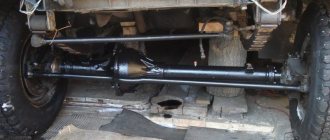
How to turn on the front axle on a UAZ
To transfer torque to the gearbox, a cardan shaft is used, connected to a transfer gearbox that has a pair of stages. Patriot cars use two types of transfer cases: Russian mechanical or Dynamos, which has an electric drive. The latter option has been in use since 2013. In both options, you cannot do without a clutch for engaging the front axle of the UAZ.
The drive is controlled using a lever or washer located on the central tunnel. To turn on or deactivate the UAZ front axle, you need to:
- Fully depress the clutch;
- Move the lever to the desired position (the modes are indicated on the plastic handle). Carry out the operation at a speed of no more than 60 km/h;
- Release the clutch: you can then drive with the axle activated. To disengage it, depress the clutch again and move the control lever to neutral.
Engaging the axle on SUVs with a Dymos gearbox is much simpler: you need to turn the washer to the desired position. The design of the transmission is such that it is not forbidden to connect the axle directly while driving. However, if a reduced speed is required, you will have to stop.
Lever options
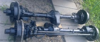
UAZ bridges
Many axle options were installed at the factory on UAZ vehicles of different models and at different times. Let's try to figure this out...
UAZ Timken bridge (civilian or collective farm)
This is a split type bridge, that is, a bridge consisting of two halves. A military bridge (also known as a gear or portal bridge) can also be classified as this type. From the factory, civilian axles are installed on UAZ trucks of the cargo range (loaf, flatbed, farmer), as well as on passenger cars of the UAZ-3151 (469) range.
Timken front civil axle for UAZ 469 and loaf vehicles Timken rear axle (civilian) for UAZ 469 and loaf vehicles Photo of the gearbox of a half civil bridge Photo of the shank of the Timken civil bridge
The UAZ Hunter is equipped with so-called hybrid axles, with a stocking from conventional Timken axles and a steering knuckle from Spicer.
Gear ratios of the Timken bridge (civilian).
Until July 1989, civil axles were equipped with a main pair with a gear ratio of 5.125 (41 teeth), now - with a gear ratio of 4.625 (37 teeth), i.e., more “fast” but less “powerful”. You can find both in stores. You will most likely have to replace the “new” with the “old” main pair when installing very large wheels. It is recommended to replace the main pairs only as a complete set (in the front and rear axles), otherwise the front axle will have to be turned on only in mud, snow, sand, etc., so as not to damage the transfer case or spoil the tires. How to determine the gear ratio? You need to twist the cardan by hand and count the revolutions of the wheel. For example, 46 cardan revolutions - 10 wheels = 4.6 pair, etc.
Main pair for UAZ, Timken axles, hybrid, 37-8, 4.625
Weight of UAZ civil bridges:
- front axle - 132 kg
- rear axle - 100 kg
Geared (military) axles UAZ
Essentially this is the Timken Bridge, i.e. split, but it has a smaller central gearbox and has final drives. The factory installed military bridges on UAZ 469 vehicles for the army and UAZ, Bars. UAZ Bars bridges are military bridges, but with a wider gauge.
UAZ military axles Photo of UAZ military axles Photo of the UAZ final drive Photo of the UAZ rear military axle UAZ Bars portal axles UAZ Bars axles installed on the UAZ Bukhanka
Gear ratios of UAZ military bridges
The gear ratio of military axles is 5.38 (=2.77*1.94 - the gear ratios of the main and final drives, respectively) - more high-torque, but less high-speed than conventional axles.
Characteristics of a military bridge
- Ground clearance: 300 mm (with tires Ya-192 215/90 R15 (31 x 8.5 R15)
- Track: 1445 mm
- Gear axle track of UAZ Bars: 1600 mm
- Weight of the UAZ front military axle: 140 kg
- Weight of the UAZ rear military axle: 122 kg
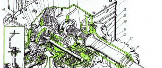
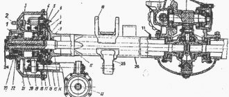
Diagram of a UAZ gear (military) axle
UAZ rear axle with final drive:
1 – main gear housing cover; 2 – differential bearing; 3,13,49 – adjusting shims; 4 – sealing gasket; 5.7 – drive gear bearings; 6.15 – adjusting rings; 8.42 – cuffs; 9 – flange; 10 – nut; 11 – mud deflector; 12 – ring; 14 – spacer sleeve; 16 – main gear drive gear; 17 – satellite; 18 – right axle shaft; 19 – final drive housing; 20.29 – oil deflectors; 21 – axle bearing; 22,26,40 – retaining rings; 23 – sealing gasket of the final drive housing; 24 – final drive housing cover; 25 – bearing; 27 – brake shield; 28 – brake drum; 30 – wheel mounting bolt; 31 – axle; 32 – hub bearing; 33.41 – gaskets; 34 – lock washer; 35 – leading flange; 36 – hub bearing nut; 37 – lock washer; 38 – bushing; 39 – final drive driven shaft; 43 – driven shaft bearing; 44 – final drive driven gear; 45 – special nut; 46.50 – drain plugs; 47 – final drive drive gear; 48 – right cup of the satellite box; 51 – main gear housing; 52 – axle gear washer; 53 – axle gear; 54 – satellite axis; 55 – driven gear of the main gear; 56 – left cup of the satellite box; 57 – left axle shaft
Scheme of the UAZ rear military axle
Steering knuckle of the UAZ front axle with final drive:
a – signal groove; I – right steering knuckle; II – left steering knuckle; III – wheel release clutch (for an alternative design, see Fig. 180, IV); 1 – oil seal; 2 – ball joint; 3 – steering knuckle hinge; 4 – gasket; 5 – grease fitting; 6 – kingpin; 7 – overlay; 8 – steering knuckle body; 9 – pin bushing; 10 – bearing; 11 – driven shaft of final drive; 12 – hub; 13 – leading flange; 14 – coupling; 15 – locking ball; 16 – protective cap; 17 – coupling bolt; 18 – axle; 19 – lock nut; 20.23 – support washers; 21 – final drive drive gear; 22 – locking pin; 24 – rubber sealing ring; 25 – thrust washer; 26 – axle shaft casing; 27 – rotation limitation bolt; 28 – wheel rotation limiter; 29 – steering knuckle lever
Diagram of the steering knuckle of the front military axle with final drive
Differences between military bridges and civilian ones
Military and civilian bridges differ in that the former have not only a main gear, but also final wheel drives. The transfer case design of these cars is identical. The transmission of the UAZ 469 increases the torque received by each wheel, so a vehicle with a military axle has much better off-road and on-road characteristics.
A significant advantage of this system is that the axle of a military vehicle with side gears is 4 cm higher than that of a civilian vehicle. As a result, the vehicle's ground clearance is significantly improved when overcoming obstacles on the road. At the same time, military axles are manufactured with an overall gear ratio that is much higher than all other designs. This results in a significant increase in torque. A car with such characteristics is slightly inferior to its analogues in terms of speed characteristics.
An engine that constantly operates at high crankshaft speeds wears out its life much faster. The gear ratio of old civil bridges is 4.625 or 5.125. This depends on the number of teeth on the final drive sprocket.
For Military axles, the gear ratio is 5.38. The final drive ratio is 2.77 and the final drive ratio is 1.94. For Spicer axles, the gear ratio is 4.111. This is for carburetor cars. The gear ratio for diesel cars is 4.625.
On civilian UAZ 469 axles, a differential with forced or automatic locking is installed on each axle. The locking drive is used in different ways:
- pneumatic;
- Electricity;
- mechanical.
When installing a pneumatic drive, the car is retrofitted with a pneumatic system of the simplest design. In addition to blocking the UAZ 469 on civilian axles, it can solve many related problems.
Different bridges in the UAZ 469 differ in track width. Civilian and military axles were once produced in widths of 1443-1445 mm. Now the plant produces blocks up to 1600 mm wide. This is basically a modern Spicer design. The axial weight of the UAZ 469 collective farm is 120 kg, military 140 kg.
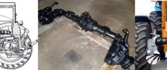
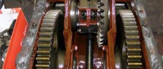
Construction of a military bridge (photo)
UAZ steering axle boot
Photo of an open side gearbox of a military UAZ axle
Image of a dismantled onboard gearbox of a UAZ car
Military bridge UAZ mushroom
Repair Gearbox UAZ 469
Assembling a pump for an IZH-Techno fire truck on a military axle
Dismantling the differential bearing of the UAZ military axle