In August 1916, the oldest automobile plant in Russia, the Likhachev plant, was founded. Initially, the company was planned to be used as an organization developing and assembling medium trucks. The plant went through many changes and improvements, was repeatedly completed and changed orientation. Constant changes did not prevent the company from creating the famous mass-produced truck and the ZIL 130 engine of the same name.
Surely, every resident of the country has seen or met this truck at least once. During the period that the car was made, which was thirty years (1964-1994), more than three million cars were produced. The ZIL engine installed on the vehicle at that time was considered a model of survivability and unpretentiousness. These qualities of the power unit allowed the car to occupy a leading position in the medium-tonnage market.
Car ZIL 130:
Short description
The ZIL 130 (508) engine was installed on ZIL-130 and ZIL-131 trucks. The design of the ZIL 130 engine had many similarities with the engine of the executive model ZIL-111, but in general the engine models had a low degree of unification. The engine volume was reduced to 6 liters, a two-chamber carburetor was installed and it was equipped with a speed limiter. Seven-liter engines are called ZIL-375 and are used in trucks of the Ural Automobile Plant. The increase in volume was achieved by increasing the radius of the cylinders to 108 mm, while maintaining the piston stroke of 95 mm.
Tuning work
The ZIL power unit with an index of 130 and a volume of six liters has good characteristics that allow the truck to operate successfully in different conditions. However, it provides opportunities for tuning work, as a result of which it is possible to improve the dynamic parameters of the ZIL engine number 130. We list the types of actions taken to change the performance of this installation:
- Boring of cylindrical surfaces, carried out to expand the area of the chambers.
- Replacing the friction wheel - a wheel with teeth is installed.
- Shaft milling, replacement of tabs.
- Replacing the sparking mechanism with a non-contact device.
- Replacing the sprayer with an injection device with one nozzle.
It is also possible to carry out other tuning work that allows you to show improved characteristics.
Source
Characteristics of the ZIL 130 engine
| Parameter | Meaning |
| Configuration | V |
| Number of cylinders | 8 |
| Volume, l | 6,0 |
| Cylinder diameter, mm | 100 |
| Piston stroke, mm | 95 |
| Compression ratio | 6,5 |
| Number of valves per cylinder | 2 (1-inlet; 1-outlet) |
| Gas distribution mechanism | OHV |
| Cylinder operating order | 1-5-4-2-6-3-7-8 |
| Rated engine power / at engine speed | 110.4 kW - (150 hp) / 3200 rpm |
| Maximum torque/at engine speed | 401.8 N•m / 1800-2000 rpm |
| Supply system | Carburetor fuel supply, K-88A carburetor, two-chamber, with accelerator pump and economizer |
| Recommended minimum octane number of gasoline | 76 |
| Environmental standards | Euro 0 |
| Weight, kg | 440 |
ZIL-130 ENGINE CYLINDER HEADS
The cylinder heads are cast from aluminum alloy AL4 (GOST 2685-63), subjected to hardening and complete aging to maximum hardness (HB 70).
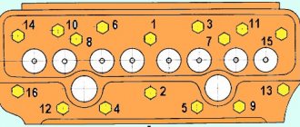
The accepted arrangement of the sockets of the exhaust (exhaust) and inlet (inlet) valves in the head (exhaust—exhaust—exhaust—exhaust—exhaust—exhaust—exhaust—exhaust) allows for channels with a smooth change in shape and sections, as well as evenly position the five bolts securing the head to the block. Twin intake ports in the head make it possible to create channels in the intake pipe that are identical in shape and length.
The head has 17 holes for bolts with M12 X 1.25 threads for attaching it to the block; four bolts go through the rocker arm axle posts.
The combustion chamber is oval-wedge type. Special studies have confirmed its high anti-knock qualities.
The introduction of cooled valves had a significant impact on the required octane number of gasoline. Thus, when using sodium cooling for exhaust valves, the required octane number decreased by 7 units at n = 800 rpm and by 5 units at n = 1800 rpm. The installation of sodium-cooled intake valves has little effect on the anti-knock properties of the combustion chamber. The required octane number decreased by only 0.5-0.6 units at the crankshaft speed corresponding to the maximum torque, and by 0.7-1.2 units at the speed at which the engine develops maximum power.
The cylinder head has holes for coolant to pass through from the cylinder block. Large holes are located on the side of the exhaust channels - in the area of the most heated parts of the head, small ones - on the side of the intake channels and serve only to eliminate vapor locks at the highest points of the cylinder block. The channels at the front and rear ends of the block heads are designed to drain heated coolant from them.
Through large holes in the block, coolant is supplied to the most heated parts of the head and, being separated in it
into two streams, discharged into the water channel in the inlet pipe through the front and rear water outlet channels of the head. In the middle of the head there is a channel for supplying oil to the valve mechanism; from the head it merges through channels at its anterior and posterior ends.
The cooling system of the block heads was subjected to detailed study and fine-tuning. The immediate reason for carrying out special work to study the efficiency of head cooling was the cases of gasket burnout, which most often occurred in winter when high-hardness water was poured into the cooling system. At the same time, the cooling of the heads could deteriorate due to the formation of significant scale in the water jacket, which partially or completely blocked some passages for the coolant, as a result of which the heat removal from the hottest areas of the head was reduced.
The temperature was measured at various points of new heads, free of scale, and heads that were in service and had a large amount of scale on the walls of the water jacket. The temperature was measured using thermocouples installed in the jumpers between the combustion chambers, under the exhaust channels and on the bosses for the bolts securing the head to the block, located at the two outer and middle exhaust channels of the head. The temperature was measured while the engine was operating in various modes over a wide range of rotation speeds and loads. The water temperature at the engine inlet varied within 30–90° C.
The tests carried out showed the following:
— the temperature of the block heads reaches its highest value when the engine is operating at maximum power (150 hp at /g = 3200 rpm) and at the maximum temperature of the water introduced into the engine (90 ° C). In this case, in heads free of scale, the highest temperature at points located in the plane of contact of the head to the cylinder block did not exceed 150 ° C, and the temperature of the bosses was 170 ° C, which is quite acceptable for the AJI4 aluminum alloy from which the head is made;
— when the load on the engine decreases and the temperature of the water introduced into the engine decreases, the temperature of the head decreases;
- in heads with a large amount of scale, the temperature of the bosses at the middle exhaust pipe is higher by about 50 ° C (* Here and below the temperature is indicated for the engine mode most often used in operation - fully open throttle at n = 2000 rpm.) than in scale-free heads.
From the graph in Fig. 26 it follows that at a water temperature of about 70 ° C (at which the thermostat damper closes), the temperature of various points of the head, free of scale, practically does not change, and the head with large scale deposits increases sharply and on the bosses located at the middle outlet pipe reaches 200° C. At this temperature, the elongation of the bosses significantly exceeds the elongation of the steel bolts located in them, which leads to an increase in the pressure of the bolt washer on the end of the bosses. If this pressure is greater than the permissible crushing pressure for the AJT4 aluminum alloy, then the boss may collapse, the bolt tightening torque will decrease and, as a result, the compression force of the head gasket will decrease and it will burn out. If there is excessive scale deposits in the water channels and they are completely blocked, large uneven heating can cause warping of the head, which also leads to a decrease in the compression force of the gasket and to burnout of both it and the head.
When carrying out the tests described above, it was established that there is a certain unevenness in the heating of the head along its length, and in some engines the heating temperature of the right and left heads was different.
To determine the cause of these phenomena, the upper walls of two cylinder heads were cut off and covered with organic glass plates. This made it possible to observe the distribution of water flows in the engine heads when cranking the crankshaft from the electric motor at different speeds with the thermostat damper closed and open. In order not to damage the plates, the water temperature in these experiments did not exceed 45 ° C and therefore the thermostat damper was forcibly opened. To facilitate observation of water flows, particles of porous plastic were added to it, the density of which differed little from the density of water.
The experiments carried out showed the following:
— when the thermostat damper is closed and the crankshaft speed is up to 1000 rpm, small flows of water are observed from the front and rear parts of the heads into the water channel of the intake pipe. In the right head, these flows are more intense than in the left, which is explained by the location of the water supply to the compressor and heater closer to the right head. The intensity of water circulation in the middle part of the head under the specified mode is less than near its ends;
— when the crankshaft rotation speed increases above 1000 rpm, a weak flow of water along the heads is established (in the right head it is more intense);
— when the thermostat damper is open and the crankshaft speed is above 500 rpm, one flow is established along the heads, the intensity of which increases with increasing speed;
- at a rotation speed of about 1500 rpm and above, the specified flow is divided into two, one of which goes to the front of the head, and the other to the rear of it. At the same time, in the middle part of the head there is an area with weak unorganized water movement.
Thus, when the thermostat is closed, the left head is cooled less effectively, and when open, the middle parts of both heads are cooled less effectively.
To equalize the flow of water in the block heads when the thermostat is closed, in addition to the bypass channel, which was used as the compressor cooling system, an additional bypass channel (bypass) was introduced, connecting the space under the thermostat damper with the suction channel of the water pump. In this regard, a new part has been introduced - the lower thermostat housing, which has a pipe onto which a rubber hose with an internal diameter of 22 mm is attached. The second end of the hose is put on a pipe molded on the water pump body. The thermostat itself is installed between the lower and upper housings.
To eliminate the area of weak water movement in the middle of the heads when the thermostat damper is open, the circulation pattern was changed so that the bulk of the water flows along the block to its rear, rises into the heads and then flows along the heads from the back to the front.
To ensure water circulation in the block heads according to the scheme described above, the diameters of the three front holes in the cylinder block were reduced (from 16 to 12 mm), the hole that supplied water to the flow between the combustion chambers of the third and fourth (seventh and eighth) cylinders was eliminated, the diameter was increased a hole located at the rear wall of the block from 16 to 23 mm, a new hole with a diameter of 16 mm was drilled next to it; the pin for installing the head on the block was made of a tube with an internal diameter of 10 mm. The holes at the end walls of the heads were changed accordingly. At the same time, to improve the cleaning of the internal cast cavities from molding soil and frame wire, the drilled holes in the lower plane of the head were replaced with larger cast ones and their number was increased (Fig. 27). To limit the amount of water flowing from the rear of the heads into the water channel in the engine intake pipe, metering inserts with 8 mm diameter holes are installed at the junction between the heads and the pipe (Fig. 28).
Tests have shown that due to the introduction of a bypass, a change in the water circulation pattern in the heads and an increase in the windows in their lower plane, the highest temperature in the area of the middle outlet pipes decreased by 25 ° C, the temperature in different zones of the head equalized and its growth stopped when the thermostat damper was closed (Fig. 26). As a result, the durability of the sealing gasket has significantly increased when the engine is operating in detonation mode.
Dosing the amount of water passing through the rear channels of the intake pipe using a special insert reduced the heating of the working mixture in it, which contributed to an increase in engine torque by approximately 2 kgf-m in the operating speed range and a decrease in the required octane number of fuel by 4 units .
Another disadvantage of the head gasket was that it would stick to the cylinder block when disassembling engines after long periods of operation. To eliminate this drawback of the gasket, the following fabrics intended for its manufacture were tested:
— asbestos steel LA-2 (GOST 12856-67), which differs from the LA-1 sheet used for serial laying in that it is vulcanized under pressure; blade thickness 1.5 mm;
— asbestos steel sheet LA-3 (formerly VLAS-L), consisting of perforated sheet metal 0.2-0.3 mm thick, coated on both sides with asbolatex mass, subjected to graphitization and vulcanization under pressure in an electric furnace; blade thickness 1.4 mm;
— asbolatex fabric LA-4, which differs from fabric LA-3 in that it is vulcanized under pressure; blade thickness 1.4 mm;
— ferronite, consisting of a metal mesh, asbestos and rubber with filler; sheet thickness 1 mm.
Tests carried out on the engine have shown that with sufficient graphitization, gaskets made from the materials listed above do not stick to the block and allow repeated installation. The LA-4 fabric, which was vulcanized under pressure and has the least residual deformation, was recognized as the best. With a small residual deformation of this gasket, the initial tightening torque of the bolts securing the head to the block is reduced slightly and at the same time a reliable seal of the joint between the head and the block is ensured.
Bending stresses in the wall of the combustion chamber are calculated taking into account the influence of jumpers using the following formula
Under the influence of gas forces, the maximum stresses in the cylinder head mounting bolts are equal to 750 kgf/cm2, i.e., significantly less than the stresses from axial forces arising as a result of pre-tightening of these bolts.
The valves located in the block head are closed with a stamped cover. A rubber gasket is installed between the cover and the block head. The valve cover mounting studs are tightened with a torque of 0.5-0.6 kgf-cm. When the tightening torque increases above 0.8 kgf-m, the contact surface of the cover to the head is deformed, as a result of which the tightness of the joint is broken and an oil leak appears.
Rice. 27. Location of channels in the head, ensuring increased circulation of coolant in it
Rice. 28. Location of the metering insert in the rear drainage channels of the intake pipe
content .. 31 32 38 ..
Cylinder block
The ZIL 130 cylinder block is cast from cast iron, with a load-bearing water jacket and insertable wet liners. To increase rigidity, the water jacket is divided by partitions into closed power circuits. The cylinder liners are cast from SCh18-36 cast iron with a ferrite content limited to 5%. An insert made of corrosion-resistant austenitic cast iron is pressed 50 mm into the upper part of the liner (this ensures a liner life of up to 200 thousand km). The thickness of the sleeve is 7.5 mm, the height of the sleeve is 188.5 mm. The camshaft is installed in the cylinder block.
| Parameter | Meaning |
| Material | Ductile iron |
| Cylinder diameter, mm | 101,48 – 101,54 |
| Diameter of boring of crankshaft supports (for main bearings), mm | 79,500 — 79,525 |
History of creation
Work on the creation of the truck began in 1953 under the leadership of designer A. M. Krieger. Initially, the car was named ZIS-125, a little later ZIS-150M. The first models of cars in 1956 were equipped with a five-liter power plant with a capacity of 135 horsepower and a maximum torque of 320 N. m. It had a V-shaped arrangement of six cylinders and was equipped with a carburetor. However, this engine was unable to ensure the operation of a medium-duty truck. It lacked the power to create the desired dynamic characteristics.
The following year, the car received a unit with six cylinders, the valves of which are located in the upper part. It was superior to the previous version in power: 140 hp. With. and had a larger working volume: 5.5 liters. However, it also did not pass verification tests. The design team settled on the following option, which turned out to be final. This option was used throughout the entire production period of the truck. The six-liter engine had 150 horsepower and was equipped with liquid cooling. The model for creating this installation for a truck was the “engine” from the ZIL-111 limousine, intended for the USSR government.
The differences between this motor and the sample were in the lower compression ratio - 6.5. This led to a decrease in power - from 220 hp. With. it dropped to 148 hp. With. The class of fuel consumed has also changed. The government limousine consumed expensive gasoline with an octane rating of 95; a work vehicle could not afford such luxury. He was switched to 76 gasoline, which was popular at that time.
Two years after the launch of the series, the plant management modernized the car and engine. During its implementation, the power of ZIL with index 130 increased slightly to 150 “horses”. This value remains until the end of the machine's production period. At the same time, the service life before major repairs was regulated - 200,000 mileage. The next modernization, carried out in 1976, made it possible to increase the service life to 300 thousand km.
Crankshaft
Crankshaft ZIL 130 steel (steel 45), forged, four-joint, five-bearing. The connecting rod and main journals are hardened. The crankshaft is made in a cross-shaped pattern for better engine balancing.
| Parameter | Meaning |
| Diameter of main journals, mm | 74,48 — 74,50 |
| Diameter of connecting rod journals, mm | 65,48 — 65,50 |
The weight of the ZIL 130 wheel is 53.75 kg, with the flywheel - 77.917 kg, with the clutch and pulley - 102.62 kg.
Piston
The pistons are cast from an aluminum alloy and coated with tin to speed up the running-in of the piston skirt to the cylinder. The piston pin axis is offset by 1.6 mm from the piston axis.
| Parameter | Meaning |
| Diameter, mm | 100,0 – 100,06 |
| Compression height, mm | 62,5 |
| Weight, g | 782 — 822 |
The piston pins are steel, floating, hollow. The outer diameter of the finger is 28 mm, the inner diameter is 19 mm. Piston pin length – 82 mm.
Service
The engine oil in the ZIL-130 engine is replaced at intervals of 6,000 - 10,000 km, depending on operating conditions. The oil volume in the ZIL-130 engine is 9 liters. What kind of oil should I use? For engines, it was recommended to use motor oils all year round up to minus 30°C - oils M-6/10V (DV-ASZp-YUV) and M-8V, at temperatures below minus 30°C oil ASZp-6 (M-4/6V,) . According to the SAE classification, SAE 10W-40 semi-synthetic motor oils can be used all year round. In regions with temperatures below -25°C, you can fill in SAE 5W-40, 0W-30 synthetics. It is also allowed to use 15W-40 mineral oil in hot climates. The engine cooling system of the ZIL-130 car contains 28 liters of coolant. Once every 40,000 - 50,000 km it is recommended to flush the cooling system. Spark plugs - A-11 or A-11B. The gap between the electrodes in summer is 0.8 - 0.95 mm; in winter it is recommended to reduce the gap to 0.6-0.7 mm.
Source