| 2 | 3 | 4 | 5 | > | Last » |
Installation of the box. Best Practices, Successes and Failures…
So, let’s move on to, perhaps, the most unpleasant procedure for every UAZ owner - installing a transfer case. The gearbox has to be removed and installed frequently: engine repair, clutch replacement, clutch release, bearing in the flywheel. And it’s not that the box is heavy... It’s just that when installing, you need to lift the box while under the car and “shoot”, trying to hit the target - the clutch disc. The procedure is still the same... It is also complicated by the fact that there is not enough space under the side of the UAZ, and the second person there is only in the way. I’m not talking about “loaves” at all, there’s simply no room there.
I propose a version of the device (unfinished, although tried). Maybe someone will improve it or make their own contribution.
Appearance of the device
It took: 1. metal plate 8mm 50x90 2. rod 12mm 90mm 3. water pipe 12 35 mm 4. half electrode. and the ubiquitous Bulgarian.
Installation takes a couple of minutes
The holes are drilled according to the holes in the beam, or at random. The same ones are drilled into the beam. Later a slot was made to insert the winch cable. The rigidity of the structure is given by the rod and small dimensions.
Next, we bring the input shaft to the seat in the clutch housing.
We hook the winch to the rear axle, or perhaps to the tow bar, on “loaves”.
The winch cable is hooked onto the transfer case, in the area of the hand brake.
And go ahead! The box is lifted and at the same time pulled forward. Make sure that the input shaft does not rest anywhere.
So, what happened: Not hard. The “adjustment” is tiny; you don’t have to remove it from the beam at all. What did not work: the tube on the device did not rotate (you need to install a bearing). The cable from the tube could come off and get damaged (you need to install limiters).
The idea of lifting it with a shovel, using it as a winch, did not work out. Although the box rises easily. It is securely secured against lowering by a lying bayonet of the shovel. But the rope stretches. But on the road, when it presses and there is a suitable cable, it will work.
Removing and installing the gearbox
Removal and installation of the UAZ 31519 gearbox
The main malfunctions that require removal of the gearbox from the vehicle are:
– increased (compared to usual) noise;
– difficult gear shifting;
– spontaneous shutdown or unclear gear shifting;
– oil leakage through seals and gaskets.
In addition, the transmission must be removed to replace the clutch, transmission input shaft front bearing, flywheel, and rear engine crankshaft oil seal.
The work of removing and installing the gearbox is very labor-intensive, so first make sure that its malfunctions are not caused by other reasons (insufficient oil level, defects in the clutch release drive, loose fastening of the gearbox and its covers, etc.).
The gearbox can be removed as an assembly with the transfer case, but for ease of operation we recommend removing the gearbox and transfer case separately. This subsection describes the removal of the gearbox and transfer case.
You will need: keys “10”, “12”, “14”, “17”, a flat-blade screwdriver.
1. Place the vehicle on a viewing ditch or lift.
2. Drain the oil from the gearbox (see “Changing the oil in the gearbox”).
3. Remove the driveshafts (see “Removing and installing the driveshaft”).
4. Remove the decorative cover of the gearbox control lever along with the front floor mat.
5. Remove three screws...
6. ...and remove the protective cover of the gearbox control lever.
7. Unscrew the pinch bolt of the terminal mounting of the gearbox control lever...
8. ...open the terminal connection using a flat blade screwdriver...
10. Similarly, remove the transfer case control lever.
11. Remove the bolts securing the hatch covers...
12. ...and remove the covers.
13. Remove the transfer case (see “Removing and installing the transfer case”).
14. Disconnect the reverse light switch wiring harness connector.
15. Remove the two bolts securing the clutch release slave cylinder...
16. ...move the cylinder to the side and secure it in any available way so that it does not interfere with work.
17. Remove the two starter mounting bolts.
18. Remove the bolt securing the clamping plate of the muffler exhaust pipe...
19. ...and remove the clamping bar.
20. Unscrew the eight nuts securing the exhaust pipe to the exhaust manifold (two nuts are installed on each stud)…
21. ...and lower the exhaust pipe down.
22. Install reliable supports under the gearbox and engine and remove the frame cross member (see “Replacing the rear suspension mount of the power unit”).
23. While holding the bolts from turning, unscrew the nuts of the lower...
24. ...and the upper mounting bolts of the muffler exhaust pipe bracket...
25. ...and remove the bracket.
26. Unscrew the nut of the lower bolt securing the gearbox to the engine.
27. Remove two bolts from the right side of the gearbox...
28. ...three bolts on the left side...
29. ...and remove the gearbox.
30. Install the gearbox parts in the reverse order of removal.
Before installing the gearbox, apply a thin layer of LSC-15 or Litol-24 lubricant to the splined part of the input shaft.
31. Fill the gearbox with oil (see “Changing the gearbox oil”).
Video about “Removing and installing the gearbox” for UAZ 31519
Installation of CLUTCH and gearbox + transfer case UAZ Loaf in One Removing the UAZ box for one UAZ 469 part 2. replacing the box on the channel Good test drive
What are the features of the gearbox on a UAZ car?
The UAZ car is common on Russian roads, is distinguished by its reliability and the ability to move on asphalt areas and off-road. The UAZ gearbox is a mechanical type with 4 steps. The mechanism is distinguished by the presence of synchronizers, the function of which is to equalize the speed. This is one of the key elements of any transport. The functionality of other systems and the quality of driving a car depend on its operation.
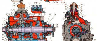
Design and principle of operation
The gearbox diagram contains information about the main and additional elements of the system. The UAZ gearbox structure includes the following units and parts:
- Fully synchronized installation, ensuring speed equalization and smooth switching.
- Primary shaft on 2 supports.
- Helical intermediate gears for shaft drive.
- An angular contact ball bearing, consisting of 2 rows and located on the rear of the shaft, is necessary to perceive and respond in a timely manner to loads arising during driving in the radial and axial planes.
- A transfer case consisting of a main axle shaft and a gear with a large working life.
Such design features make it possible to move in reverse. The mechanical type of gearbox has the main advantage of a long service life. A car with such a device copes well with difficulties while driving over rough terrain.
Malfunctions and repairs
The first signs indicating a malfunction of the automotive system should force the car owner to carry out diagnostics. In some cases, this can be done on your own. Simple breakdowns can be repaired with your own hands. It is better to entrust more complex faults to a service center.
Signs indicating the need to repair the UAZ gearbox:
- deterioration of management;
- squeaks and extraneous noises when changing speeds;
- independent activation of transmission.
In most cases, when uncharacteristic noise is observed, the cause lies in wear or defect of the bearings and gears. Stiff gear shifting indicates a malfunction of the synchronizers.
The main reason for the problems that arise is the natural wear and tear of parts.
The need to check the transfer case is indicated by deterioration in wheel adhesion to the road surface and increased noise levels from the area where the unit is located. Damage is caused by: careless operation of vehicles, untimely maintenance, use of low-quality consumables, fuel and gear oil, lack of control over the volume of working fluids.
Another group of problems is related to the leakage of the oil mixture from the gearbox. Possible reasons:
- exceeding the maximum oil volume in the box;
- water entering the system when refueling;
- a crack on the unit cover or on the crankcase.
The UAZ high-speed gearbox consists of a large number of working elements and components. Their normal functioning and interaction ensure reliable use of vehicles. Gearbox repairs will not be required if you regularly inspect your vehicle.
Mechanism adjustment
After assembling and installing the new switching mechanism, it is necessary to adjust the rods and the entire system. The goal is achieved by changing the length of the vertical and horizontal rods. Do-it-yourself setup sequence:
- Move the gear shift lever to the neutral position, and move the element responsible for selecting the gear all the way.
- Move lever 1 to positions corresponding to speeds 1 and 2. While checking that the elements are not pulled up, connect and secure the selection rod.
- Similar actions must be carried out for other gear stages.
After work, you should check that the gears are fully engaged by starting first gear and reverse. The lever must not come into contact with other parts or controls. The optimal gap size is up to 3 mm.
How to disassemble
Before repairing a 5- or 4-speed gearbox (new model), you must carefully study the device diagram, prepare material and tools. To dismantle the unit yourself you will need:
- wrenches: open-end and socket;
- screwdrivers;
- hammer;
- assembly shovel.
The large weight of the product due to contact with the dispensing system requires an assistant during operation and removal of the box.
Disassembling the gearbox occurs in the following sequence:
- Fixing the machine above the inspection hole.
- Removing transmission oil to reduce unit weight.
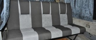
- Removing the seats in the cabin.
- Dismantling the speed release fork, clutch pan near the muffler, frame, speedometer shaft and cardan.
- Disconnecting the dispensing system from the main structure, securing it to the side with a rope.
- Removing fasteners.
After this, you can remove the body from the car. The next step is to disassemble the gearbox stages, check all elements of the mechanism for wear, and replace non-functional parts with new ones.
How to assemble
Assembly and installation of the automatic transmission is carried out in the following order:
- Placing the box in place, tightening the bolts and other fasteners.
- Attachment to the main structure of the transfer case.
- Installation of the speed release fork, clutch pan near the muffler, frame, speedometer shaft and cardan. At this stage you can assemble the lever.
- Installation of seats in the interior.
- Filling the container with new transmission oil.
After this, you can remove the car from the inspection hole. To install a new gearbox on a UAZ and replace other parts, first carefully read the mechanism diagram.
Replacing the transfer case
When installing new components, you should use only high-quality parts that are suitable for the vehicle model. This is the key to a comfortable ride and reliable functioning of all elements of the system.
Replacing the transfer case is complicated by its connection to the gearbox, which increases the weight of the structure.
The process includes the following steps:
- Removal and disassembly of the unit.
- Fault diagnosis.
- Replacement of worn elements or installation of a new transfer case.
To dismantle the device you will need:
- secure the vehicle in the inspection hole;
- lower the parking brake lever;
- move the remaining elements for selecting and changing speeds to the neutral position;
- remove the casing, handles, all connecting wire elements, covers and lining.
The new unit must be installed in the reverse order.
Timely maintenance, diagnostics of main and auxiliary components, regular replacement of worn parts, use of high-quality fuel and oil mixtures, consumables, careful operation of vehicles and following the manufacturer’s recommendations will help to extend the service life of the mechanism.
UAZ 2206 Uazka › Logbook › Removing and replacing manual transmission
At home I quickly unscrewed everything, fortunately there wasn’t much there, and removed the box into one, exactly as in the video:
I discovered that I had a dead release bearing, oil leaks from the shanks, from under the gearbox and manual gearbox connections, a dead gearbox bearing where the front driveshaft is screwed, and the reduced gearbox also came out under load.
I twisted the purchased used box, opened the manual transmission cover, the teeth were all intact, everything seemed to be moving. I found a completely dead bearing on it in the place where the drum with the brake pads is. It will be interesting to see her in action, whether she is alive or dead, as I put it, we will see.
I didn’t have time to take a photo because... repaired one and was in a hurry. In the near future it will also be assembled into one. With God's help, I'm thinking of rebuilding the manual transmission, which is 76 kg.
UAZ loaf gearbox device. UAZ loaf gearbox
Gearbox cover UAZ loaf
The gearbox cover on a UAZ loaf, like on any other car, is an important part of the gear shift control mechanism - if a malfunction occurs in it, driving the car is either impossible due to the inability to engage the gear, or is dangerous due to the fact that only some of them work from the steps.
The cover itself is the main part of the gearbox. In this regard, in case of any problems with the lever or suspicious noises from the box, it is recommended to check its condition - perhaps this part needs a complete replacement rather than minor repairs.
Repairing the gearbox cover on a loaf
For example, in a situation where the bushings are worn out, you can do the following: make new bushings and put the cover back, first boring out the space for it (in this case, the axles are replaced with completely new ones).
Oil dripping from axles due to worn bushings can be eliminated in another way. To do this, you will need to remove the levers, cut off pieces of small thickness from a pre-selected hose that is resistant to oils and gasoline (which is selected individually for the cover), insert them onto the axles and tighten them with the levers.
In this case, the levers will turn a little tighter, but the gear shift speed will remain the same.
Some users, if they encounter similar problems associated with wear of the splines on the axles and non-engagement of gears, advise not to repair the cover, but to purchase a new one.
In this case, the new UAZ loaf part must be upgraded before installation. To do this, fluoroplastic bushings are installed in place of the rubber bushings.
The removed bushings are cut and installed on the shafts under the levers, which ensures the absence of backlash and protects this part of the mechanism from dirt and water getting into it.
If one of the gears starts to slip out, it’s worth checking:
Most often, the reason for knocking out gears lies in worn gears and balls, as well as broken springs.
In addition, before repairing the gearbox cover, you should pay attention to the general condition of the mechanism - perhaps a major breakdown, which is clearly noticeable, hides several minor problems, or the entire mechanism is so worn out that it would be wiser to replace it with a new one.
Control mechanism, gear shift of the UAZ-452 gearbox
The gear shift mechanism of the four-speed semi-synchronized gearbox of the UAZ-452 family is mounted in the side cover of the gearbox. The gearshift forks are attached to the rods using a conical screw pinned with wire.
The movement of the forks when shifting gears occurs together with the rods, which have a socket for a locking screw and grooves for clamps and a locking device. The middle rod also has an intermediate pin of the locking device. When one of the gears is engaged, the rod moves and locks the adjacent rods with a rod through the cracks.
Thus, each of the remaining rods is locked with a key lock and cannot be moved out of the neutral position until the previously switched rod is returned to the neutral position. The same lock prevents two gears from being engaged at the same time.
The forks in the neutral position and in the positions with the gears engaged are fixed with balls. To switch the forks, a clutch with a lever is used, mounted on the splines of the vertical shaft. The head of the clutch lever fits into the grooves of the forks. The coupling can move along the roller in the axial direction. When the shaft rotates, the clutch rotates and its lever moves one or another fork.
In this case, in the uppermost position, the clutch is connected to the first and second gear forks, in the middle position - to the third and fourth gear forks, and in the lowest position - to the reverse fork. The middle position of the coupling is fixed by the coupling resting on the washer against which the spring rests. In order for the clutch to reach its lowest position, additional force must be applied to compress the spring. The outer end of the shaft is splined and threaded to accommodate the gear shift lever.
To move the coupling up and down, there is a control lever that rotates on the shaft and fits into the groove of the coupling. The outer end of the roller has splines and threads for attaching the outer lever. The rollers are sealed with round rubber rings.
The outer control and shift levers have a slotted hole at one end, and holes at the other end into which rubber pads with brass bushings are inserted. When installing control and shift levers on the splines, deviation from the positions is allowed within 5 degrees in any direction.
Positions of the outer gear shift levers.
Control mechanism of a four-speed gearbox UAZ-452.
This mechanism consists of two levers - control and switching, rotating in mutually perpendicular planes. Both levers are installed in a bracket that is attached to the cab. At the end of the long arm of the control lever there is a hole for connecting the rod; at the end of the short arm there is a fork into which the lever fits. In the middle position, the lever is fixed with a locking ball.
The shift lever is connected at one end to the rod, and at the other to the main gear shift lever using a forked protrusion with holes. The main lever is mounted on an axis that is screwed into the body of the shift lever. The axle is locked with a locknut. The main shift lever hinge is protected from dust by a polyethylene seal that covers the hole in the cabin air duct. The edges of the hole are sealed with foam rubber, pressed with a steel clip.
The main lever first rotates laterally relative to the shift lever and then rotates only with the shift lever to engage the desired gear. The vertical rod is attached to the control lever using a pin, cotter pin, flat and spring washers. The shift lever is connected to the vertical rod with a pin and a cotter pin.
The lower ends of both rods have threads that allow you to change their length. To adjust the length of the rods, pins are placed on their threaded ends, secured with two nuts. By unscrewing or screwing the nuts, you can change the length of the rods without disassembling the connection.
The cylindrical parts of the pins with square heads are connected to the intermediate arms using cotter pins, flat washers and spring washers. The intermediate lever assembly is mounted on the second cross member of the vehicle frame. All intermediate levers are mounted on one axis: the upper intermediate control lever is knurled, the lower intermediate control lever is secured with a radial pin, the intermediate shift lever is freely mounted on a bronze bushing. The axle has holes for lubricant supply.
The intermediate levers are connected to the gearbox levers by horizontal rods, the opposite ends of which are connected to the gearbox levers using pins with square heads.
Operation of control and gear shift mechanisms of the UAZ-452 gearbox.
The lever in the cabin can move in two planes - parallel to the axis of the car and perpendicular to it. When this lever moves perpendicular to the axis of the car, its lower end moves the control lever and, through a system of rods and intermediate levers, inserts the shift clutch into the desired position.
When the horizontal rod moves backward, the shift clutch is connected to the first and second gear forks, and when moving forward, it is connected to the reverse fork.
When the lever moves in the cabin in a direction parallel to the axis of the car, the gear selected by the previous movement is switched. The control lever of the control mechanism remains stationary, and only the shift lever rotates.
Adjustment of control mechanisms and gear shifting of the UAZ-452 gearbox.
The control mechanism and gear shift mechanism after adjustment should ensure proper operation of the gearbox and comfortable operation for the driver. The adjustment procedure is as follows:
— Set the levers on the gearbox cover to the neutral position. — By changing the length of the horizontal rods, install the intermediate levers so that their lower arms are directed vertically downward. — By changing the length of the vertical control rod, install the mechanism control lever on the lock. — Then select the length of the vertical shift rods so that the lever handle in the cab is in the middle position between the instrument panel and the hood.— Securely fasten the rod nuts.
By sequentially engaging first gear and reverse gear, you need to check the correctness of the drive adjustment. In these positions, the rods and intermediate levers should not rest against adjacent parts. The lever in the cockpit should not come close to the instrument panel or hood so as not to injure the driver’s hands. The gear engagement in the gearbox must be complete, that is, the engagement rod must be in the locking position.
Installation of the gearbox together with the RK on the UAZ 452 without assistants
This is a machine translation of a Ukrainian article. You can read the original here.
My repair of the UAZ Bukhanka gearbox: removal, repair, installation
Yesterday the following situation occurred: when the car was moving, a crashing sound occurred and all gears stopped working. That is, when you engage any gear and try to move, the gears crunch and the car does not move. Few people undertake to make these machines, and those who do have a waiting list. You'll have to do it yourself.
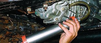
Now I will unscrew the cardan and remove the gearbox. I will try to repair it myself. I unscrewed the box mounting bolts: on one side there are 2 bolts; on the other side there are 2 bolts. I placed the pallet. Now I'll try to remove it. So she sagged. That's it, the box is removed. I'll take it out now and inspect it.
I removed the box, now I’ll disconnect it from the transfer case. And immediately what catches your eye is this play, the play of the input shaft. It is still a mystery to me how I will put it in place, but time will tell. I disconnected the transfer case from the transfer case, and the second thing that caught my eye was that this nut was unscrewed. And it looks like we have a left-hand thread.
How to remove the body from the UAZ loaf frame
How to remove the body from the UAZ loaf frame
First of all, we dismantled the passenger compartment, since the floor was covered with plywood and there was no other way to get to the bolts securing the frame to the body. Advice for Loaf owners - if you want to preserve the body, then treat it inside with anti-corrosion mastic and make a couple or three holes for drainage and ventilation in the floor. We removed the plywood and raked out 7-10 kg! wet sand and earth. The state of the floor is sad, but that is a topic for another day.
So let's get started. The body is attached to the frame with ten “furniture bolts” and this is no joke. Six of them are in the passenger compartment, two behind the front wheel arches, two at the feet of the driver and passenger. The bolts are secured at the bottom with second nuts.
Before we begin dismantling the bolts, we disconnect the battery, disconnect the ground from the engine - behind the hood compartment and raise the car on a lift.
Next, we disconnect the wires from the starter (in our case, the starter and the wiring to it were new and we took into account the length of the wires for the elevator; if the wires are standard, they may be short).
Next, we disconnect the radiator fasteners from below or from above (we disconnected from below, but then during installation we left the standard lower fasteners, and slightly modified the upper one in place)
Disconnect the gearbox lever drive rods and the brake booster rod.
Then, drain the coolant (don't forget to open the radiator cap), and remove the hose from the heater.
We unscrew the support for fastening the transfer case levers and the fasteners for the sump filter of the pumping line between the tanks.
After this, completely unscrew the nuts from the six rear body bolts and loosen the front nuts. At the same time, since the fasteners are old and rusty, and the bolts resemble “furniture” bolts with a tetrahedron under the hat, you need to act carefully; if the bolt turns in the body, then there will be nothing to hold it, and this is extra work to weld a nut or bolt to it etc. Therefore, holding one nut with a wrench, use the head to unscrew the lock nut, and only then the main nut.
There is nothing else to do under the car for now, lower the car onto the wheels and disconnect the steering column and unscrew the boot on the floor.
Actually, when all this is done, you can begin lifting the body over the frame. We perform the operation by placing stops under the wheels so that the car does not move. We start lifting from the rear of the car, keep in mind that when removing the load from the frame, it rises on springs and if you lift the body with jacks, then you need a good headroom. We lifted it with a lift and didn't have this problem.
So, we tear the body off the frame by about ten cm and be sure to place a safety wide wooden beam between the frame and the body. Next, take out the standard bolts and drill holes with a diameter of 12 mm. Standard bolts are 10mm.
The spacers will need some modification. In our case, these were welded barrels 6.5 cm high. On the last and middle spacers, it is necessary to cut off a small sector at an angle of 45 degrees, because there are protrusions on the frame. And the rear “barrels” should be 1 cm higher than all the others, but we all had the same ones, so we had to put 5 wide washers.
Next, we insert four rear spacers, insert bolts and attach nuts to two bolts closer to the middle of the body. We also raise the body and insert middle spacers. At the same time, we increase the size of the belay lining with the help of boards to approximately 150 mm. Remove the nuts from the front bolts. We remove the insurance and lower the body.
We roll the car over, fix it, remove the standard bolts and begin lifting the body from the front. First, we insert the spacers and front bolts, and attach nuts to them. The front bolts should be 180-200 mm. The remaining 150 mm.
Next, we raise the body further and insert a second pair of spacers and bolts. We lower the body. We tighten all the fasteners from the center to the stern and then to the front. We used wide washers and self-locking nuts, but you can also use locking washers and regular nuts if you like. Bolts with a strength of at least 8.8, and preferably more. And preferably with fine thread.
Now the most interesting thing is that we need to secure everything that we unscrewed, but the body rose by 6.5 cm.
We do the following, we lengthen the rods by welding inserts (don’t forget to paint them or treat them with anti-corrosion agent)
Place the rods in place and secure them with cotter pins.
Next, we make a support for attaching the transfer case control lever
We put it in place and fasten it with long (90mm) M8 bolts
We make a filter support and also put it in place
Now the most difficult thing, after lifting the body, the steering wheel began to lie on its eggs. ah, sorry on the stomach. We need to make an adapter bracket for the steering gear, like this.
Please note that the heads of the lower bolts must be cut so that the rod does not touch them. After that, the steering column and its boot were secured.
We put a new, longer hose on the heater, tighten the clamps, and fill in antifreeze.
Well, all that remains is to screw on the new extended ground wire and the radiator, connect the battery, install the big wheels (in fact, it was for them that everything was started) and you can be free - INTO THE PAMPAS.
Finally, photos of the spacers between the body and frame. They fastened it rigidly, without any rubber bands, since both the frame and the body of the loaf are not very strong, and this gave some reinforcement. Although, if you prefer, it would be better to strengthen the frame with additional spacers and gussets.
Suspension lift UAZ Bukhanka
Pros and cons of a suspension lift
Now let's look at the next way to carry out a UAZ Bukhanka lift - a suspension lift. As already mentioned, this method has both pros and cons. There are two main advantages of the suspension lift on the UAZ:
Well, the main disadvantage of this method is the inevitable increase in the angles of the universal joints. In this case, the cardans are put into operation for wear.
There are several options for carrying out a suspension lift. Let's look at some of them.
Installing longer spring shackles
The simplest and most affordable option is to install longer spring shackles. When carrying out a suspension lift in this way, you should not get too carried away with it, so as not to install too long ones. Spring shackles that are too long can negatively affect the performance of the suspension and affect handling. To avoid problems with handling, it is recommended to tighten the earrings with a tie in the center.
Bridge-spring spacer
Without disturbing the design of the springs, it is possible to slightly raise the Bukhanka’s suspension by installing a spacer between the bridge and the spring. At the same time, you don’t have to wait for a big elevator; here it is also recommended not to get carried away with the process.
Of course, when installing such a spacer, it is necessary to decide on its fixation in the installation location, and also to calculate that the length of the spring ladders is sufficient. It is also possible to restore old springs, or purchase new ones. There are also special elements for such tuning on sale, but they are usually very expensive.
Spring preload
Springing springs is not as complicated as it might seem at first glance. This process is useful not only for the sake of a suspension lift, but also for the purpose of making the UAZ’s hard suspension soft enough. However, despite the fact that there is an improvement in the performance of the suspension from this method, they are very insignificant.
If you decide to give it a try, you'll first need to cut, grind, or buy spacers, rubber, conveyor belt, and metal. And most importantly, when lifting the UAZ suspension, longer-stroke shock absorbers will be required, since the rebound of the old ones will begin earlier.
In conclusion, I would like to note that the main thing is to know moderation in everything. When you take on tuning the UAZ 452 with your own hands, remember about your safety. After all, you will not have a guarantee if you do the Loaf lift yourself.
Removing the body or cab
Removing the body or cabin for repair or replacement is carried out in the following order:
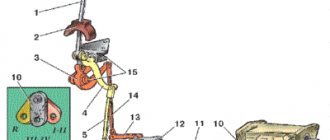
Frame and body design of UAZ-469, UAZ-31512, 31514
frame (Fig. 1) consists of two longitudinal beams 3 connected by five cross sections.
Four transverse elements are welded to the longitudinal beams by electric arc welding, one transverse element 8 (the second front) is attached to brackets welded to the longitudinal beams of the frame.
To the back of the frame there is a cross mounted towing device (Fig. 2) of a double-acting closed type, which is equipped with a rubber elastic element 4, which softens shock loads when moving a car with a trailer out of place, as well as when driving on an uneven road.
Maintenance of the towing device consists of periodically cleaning from dirt, checking its condition and reliability of fastening of the rear part of the transverse frame , as well as lubricating the friction surfaces in accordance with the instructions of the lubrication card.
This is achieved by adjusting the bearing nut 2 (see Figure 2) with the shaft hooks. The latch should tightly close the throat of the hook and securely secure the dog.
The rubbing surfaces of the support nut 2 and the hole in the housing 3 are lubricated with lubricant placed under the cover 1 when assembling the towing device.
Removing the body from a UAZ mp4
breeding body work
with UAZ
,if you can call
bodywork
:))) Fix Life is a channel of useful ideas and information.
Connecting the frame to the body part3
Joining the frame with body work
Now we will disassemble the gearbox itself
I unscrewed the cover and unscrewed the flange mounting bolts. Now let's see what's inside. I don't see anything drastic yet. I'll take a look now, and if anything happens, I'll tell you. Apparently, this was the problem. This block of gears, this shaft is all shaking and dangling. And here the lid squeezed out, which should be screwed on.
Apparently, the problem is in this gear block bearing, because sometimes the entire shaft does not engage because it is loose. And the synchronizer has practically no teeth. I have a familiar VAZ specialist nearby, I will now consult with him and continue the repairs.
I consulted with a specialist and they said that both the intermediate shaft bearings and the input shaft bearing need to be replaced. They told me not to touch the worn-out synchronizer, just leave it like that, because there were no crackers or balls there. It will work fine. We also need to change the oil washer.
I went to the store and bought bearings: 50 208 with a groove for the input shaft; 50 306 for the intermediate shaft. I also need an open 305 bearing without groove, but there was no open one, so I bought a closed one. Then I’ll remove these rubber things - it will be open. Also sealant, gaskets for the box, oil drain washers and bolts for the cardan.
Now we will disassemble the box. To remove the intermediate shaft, you need to remove these gears. To do this, I unscrewed this bolt. It needs to be unscrewed. Now I will knock out the axle. That's it, knocked it out.
Now we will knock out the intermediate shaft itself. To do this we need to unscrew this nut. And you will have to hit the bearing from that side so that it falls out here. Now let's see how it turns out. It was not possible to unscrew this cap because it was squeezed out and did not fit the thread. I just broke it. I don’t know if these are on sale or not, it’s aluminum. Look what happened to the bearing - there is practically nothing left of it.
Now we need to press out the input shaft. There is a place here on the gear where there are no teeth. It must be placed so that it does not interfere with the exit, so that the teeth do not cling to this gear. We've twisted it, we've installed it, now we'll press it out. I found an iron screwdriver, I’ll install it now. This input shaft came out very easily.
Let's go further. We pulled out the primary shaft, now let's move on to the secondary shaft. You need to unscrew these bolts, remove this lock washer, and hit the bearing there so that the bearing comes out. I have already unscrewed these plates that held the bearing in the groove. Now I remove the lock washer, then I remove this washer. Now you can hit the bearing so that it comes out. Now I will press out the bearing with hammer blows. I need to pull the bearing out of here, I'll try now. After removing the bearing and removing (inaudible 09:35) the washer, I pull out the output shaft.
To remove the intermediate shaft, you need to unscrew this nut and drive it in there. Now let's try how it will be. I unscrewed the intermediate shaft nut, there was a race from the bearing left, and now we will pull out the gears. He understands everything here and should come out that way. We collect them so as not to forget how they stood. Now I’ll wash, clean and start replacing parts and assembling the box. The box has been disassembled, now I will clean this centuries-old dirt with a scraper. Then I’ll try, I have a cutter, I can use a torch, I’ll burn it all so that it’s clean. Only then will I collect everything.
We install the intermediate shaft. First we put on the ring, then the small gear, then this smaller one will go. Then we put the big one like this. We’ll just insert everything inside, so we’ll take it all apart again.
Now we will press in bearing 50 306. This side is pressed in, let’s move on to the other side. Now we press the bearing on the other side. Install the secondary shaft. We glued the rollers to the solid oil, now we will insert them into the secondary shaft. That's it, there's nothing more interesting here yet. Now we will collect everything and connect it to the distribution box. The most interesting thing will begin when we put it in place.
To insert the box into the transfer case, you need to remove the hatch on the transfer case and adjust the gears by hand. It should coincide with the secondary shaft. Using all kinds of pads, I display the box like this. Now I will try to push her there. I do the work alone, I don’t know whether it will work or not. While I can’t get the box underneath, I stuck it there, but didn’t hit the clutch yet. When I was redoing the floors in the loaf, they all rotted, I provided a hatch like this, it is held on by bolts. Now I’ll try to lift it from here with ropes and insert it.
Also, look who will remake the body of the loaf, I have such a table. I have it open on bearings, and there is access to the rear of the engine. Now I will try to lift the box from here. Everything, as we see, the box has settled into its fastenings. The hatch helped, but only two holes would be enough to pull the rope through. That is, I stretched out the rope, tied it in a knot, began to twist it with a crowbar, and the box began to rise. I hope I did everything right. That's it, let's collect further.
After twisting a few turns, the box was lifted to the end, and now you can easily tighten the fastenings of the box cushions. So the hatch passed the test - it’s a necessary thing. That's it, the work is finished.
It took me 1,500 rubles for the materials: all the gaskets, oil, bearings. Last time I repaired the gearbox at a car service center, the first gear fell out, and they charged 10,000 rubles. Today I had to do it myself, but saved money.
Source
Step-by-step instructions for repairing the UAZ gearbox (loaf)
The UAZ (loaf) car is one of the most common cargo and passenger vehicles, which has a spacious body, an impeccable safety system and a durable power unit. This is a fairly reliable car, however, during intensive use, malfunctions and breakdowns occur that require immediate attention.
In most cases, UAZ gearbox repair
necessary due to normal wear and tear, which indicates the excellent reliability of this device. The main reason for the premature failure of this unit is that there is an increased level of fuel in the system, so it is necessary to use oil of impeccable quality.
If this recommendation is not followed, noise of a special nature may appear in the design of the unit. The synchronizer or its internal components may also fail, which always results in difficult gear changes. These are not all the breakdowns that cause the need to repair the UAZ “Bukhanka” gearbox.
.
The main signs of gearbox failure:
If these problems occur, the device should be diagnosed to accurately identify the cause of the breakdown. This will save time in the process of repairing the UAZ gearbox.
, and will also contribute to a high-quality restoration of functionality. It is recommended that this procedure be performed by specialists.
The main tools needed to restore the transmission's functionality:
Repair of UAZ “Bukhanka” box
consists of a number of steps that must be performed one by one. In the process of professionally restoring the performance of a gearbox, qualified technicians perform a number of actions.
Dismantling the gearbox
The transfer case and gearbox of UAZ vehicles are attached to each other into one unit, which is the correct technical solution. This unit weighs more than 80 kg, so it is extremely difficult to remove it yourself.
Before you start repairing the UAZ gearbox
the vehicle needs to be placed on a level surface, since during restoration activities it will be necessary to move back and forth by approximately a meter. After draining the oil, you should remove the seats, clutch release forks, and the two halves of the hatch. In addition to the above, components such as brake system levers and suspension mounts in the chassis are subject to removal. This will make it possible to extend the checkpoint.
Restoring gearbox functionality
Detection of defects in component parts is possible after complete disassembly of the unit. Based on this, in consequence, it seems possible to repair the UAZ “Bukhanka” gearbox
. All components are washed in kerosene and dried.
This will make it possible to more effectively detect any breakdowns or damage. Particular attention must be paid to the shafts and crankcase. In case of any malfunctions, chips or other damage, each component is replaced with a new component.
Disassembly and installation
After repairing the UAZ “Bukhanka” box
, you need to install the device in place in the car. The most important and responsible action is to mount the input shaft into the clutch. With slight translational movements, moving the gearbox up and down, the unit is installed in place.
Grovers with nuts are inserted on the left side. Next, the clutch fork and spline oiler are mounted. Upon completion of the previous step, you need to insert the speedometer drive and other parts. Next, the frame cross member and muffler bracket are secured, after which the hand brake mechanism is calibrated.
Why are our partners' clients always satisfied?
Our partners carry out highly qualified repairs of the UAZ “Bukhanka” transmission
at a high professional level. Our specialists have specialized knowledge and significant practical experience, and use functional tools. This makes it possible to guarantee each client the impeccability, efficiency and reliability of the UAZ gearbox repair performed.
If you have any questions, please contact us, and our specialists will give comprehensive and competent answers to all your questions.