Basic clutch malfunctions
The main causes of clutch malfunctions:
- Flywheel wear. Cracks, scuffs and other defects may appear on the surface of the device. Grinding can be used for restoration, but it must be carried out taking into account the manufacturer's tolerances. When diagnosing, you should also check the condition of the ring gear of the starter mechanism.
- Failure of the support bearing. A jammed or jammed part may make it impossible to disengage the clutch. In case of wear, extraneous sounds may appear.
- Faulty seals. When the parts wear critically, the clutch does not work correctly.
- Failure of the release mechanism. When replacing the system, this part must also be changed. The release device must slide freely along the guide sleeve. It is also important to always check the correct installation of the latter. The bushing is located parallel to the transmission input shaft.
- Worn clutch cable. If the problem is a broken product, it is replaced. In case of stretching, adjustment will correct the problem.
- Oil leak. Lack of lubrication leads to the fact that the unit begins to run dry. Oil is required for processing splines and guide bushings for bearings. It is important that the lubricant contains no solid metal particles. After the splines have been processed, the remaining substance should be removed.
The main thing during repairs is to use original spare parts for the DT 75 tractor, and entrust the restoration procedure to professionals. Low-quality components do not last long, and errors during the replacement process can lead to more serious malfunctions.
Maintenance, monitoring and adjustment of transmission elements and gears
Adjustment and adjustment work carried out during maintenance are intended to restore normal fits and clearances in the joints that were damaged during operation as a result of wear. The adjustment work performed during maintenance is extremely diverse, but they are all subject to general principles, which should be considered according to the main groups of mechanisms, kinematic pairs, etc. Technological adjustment work is preceded by inspection and diagnostic work, during which faults and technical malfunctions in machines and their elements, and also measure the gaps between mating parts and assembly units, and the need for certain adjustment work is established. During the maintenance of road-building machines, all their elements are subject to adjustment work. The work is performed in the following sequence: internal combustion engines, their mechanisms and systems, transmission elements, gears, support devices and bearings, brake systems and clutches, control mechanisms and levers, control systems, running gear. Transmissions of road construction machines (bulldozers, scrapers, graders, etc.) consist of clutches, gearboxes, power take-off mechanisms, reversing mechanisms, drive axles, gear and chain drives. The technical condition of the transmission is assessed primarily by the total lateral clearance between the teeth and splines of the gears, and the wear of gear and chain drives. For these purposes, the KI-4813 device is used - a backlash meter (Fig. 7.6). The device consists of a body, at the base of which there is a magnet, an arrow-pointer, a scale with divisions, and a torque lever with a set of interchangeable heads for turning the drive sprockets or wheels. The magnet is designed to secure the device to parts of the transmission - hub, axle shaft, etc.
Rice. 7.6. Checking the total lateral clearance in power transmission mechanisms using a KI-4813 backlash meter: 1 - backlash meter; 2 - torque lever
During inspection, pay attention to signs indicating the condition of the gears: external damage, oil leaks from the crankcases, abnormal noises and knocks, vibration, increased heating. Friction clutches (disc and cone). The frictional forces developed between the clutch discs or pads must be greater than the greatest forces transmitted from the engine shaft. The main indicator characterizing the reliable operation of clutches is the safety factor, which shows how many times the friction torque created by the discs or pads exceeds the torque transmitted from the engine of the transmission mechanism. During the operation of clutch couplings, the safety factor gradually decreases due to a decrease in the friction moment, which is a consequence of wear of the rubbing surfaces (discs, pads) or misadjustment of their relative position. As a result, the prestressing forces of the driving and driven elements of the clutches decrease, which leads to slippage, as well as to an increase in the stroke of the pressure (drive) disk, the cone of the block when the clutches are turned on, and to a weakening of the pressure levers (for non-permanently closed clutches) or pressure springs (for permanently closed ones). couplings). The performance of friction clutches is ensured by adjusting and replacing their working elements (friction discs, pads, bands, etc.) that have become unusable. The performance of the couplings is checked at maximum load. During testing, when the maximum load is selected, the power engine must stop due to gear overload, and the clutch must operate without slipping. A properly adjusted clutch should not slip when the engine is overloaded; at the same time, it should ensure easy switching on and off with complete connection and disconnection of its working elements. The gaps between the discs in single-disc couplings should be in the range of 0.35-0.45 mm. In double-disc clutches this gap ranges from 1.5 to 2.0 mm. The gap size is checked with a set of feeler gauges, and adjustments are made in different ways depending on the design features of the adjusting devices. The free play of the pedal to engage the clutches should be 20-40 mm, depending on the purpose of the clutch and the design of the control mechanism for this clutch. The distance between the ends of the release levers and the release bearing ring is in the range of 3.5-4.5 mm, and the difference in these gaps for individual levers should not exceed 0.3 mm. The indicated dimensions are checked with a feeler gauge when the clutch is engaged. Friction clutches are adjusted in the off and neutral positions of the gear shift levers. The coupling is considered adjusted if its activation can be carried out with a foot-operated force of no more than 60-80 N, with manual activation - 120-160 N, and the gap between the flange and the coupling should be within 9-11 mm. If the force is less than 120 N when activated manually, and the gap is less than 4-6 mm, the clutch is subject to additional regulation. To ensure normal operation of the couplings, it is necessary to lubricate their bearings systematically (in accordance with the instructions). As an example, the adjustment of friction clutches of various designs is considered. The clutch of the T-130M tractor (Fig. 7.7) is multi-disc, permanently closed, with mechanical closure of the friction discs. The coupling in question does not represent a separate removable element, and its assembly units are built into the engine flywheel, although they can be removed without dismantling other elements of the machine. In order to check and adjust the clutch associated with the servo mechanism and the locking mechanism, connect the output lever of the servo mechanism to the tap, rod, pin, nut, and ball nut. Then unscrew the plug from the servomechanism and attach the control system pipelines to it. After this, a gap of 9-11 mm is established between the flange and the coupling, and a gap of OD-0.2 mm is established between the ends of the levers and the coupling, and the free travel of the servomechanism rod is adjusted by screwing in and out the shock absorber on the pedal column so that, between the servomechanism rod and the push rod the lever had a gap of 0.9-1.11 mm.
Rice. 7.7. Scheme for adjusting the clutch control system of the T-130M tractor: 1 - switch lever; 2 — pull-out pin of the clutch engagement lever; 3 — clutch brake disc; 4 — bearing housing cover; 5 - layering; 6 — cardan shaft; 7—clutches; 8— driven drum; 9 — support; 10 — external pressure spring; 11 — support disk; 12 — pressure disk; 13 - drive disk; 14 — driven disks; 15 — engine flywheel
When adjusting (with the engine not running), first use a ball nut (located inside the clutch housing) to set the free play of the servo rod (13-15 mm), equal to the amount of recess of the rod when pressing the pedal. Next, they begin to adjust the locking mechanism with the clutch engaged, for which the lever is set with an adjusting fork so that it is tilted forward (along the machine) by 15-21°. In this case, the marks on the clamp rollers should coincide with the marks on the roller bodies. Then check the ease of movement of the servo rod and clutch pedal with the engine running.
Rice. 7.8. Scheme for adjusting the clutch control system of the DT-75M tractor: 1 - locking mechanism rod; 2 - emphasis; 3 — main clutch control lever; 4 - adjusting screw; 5 — servomechanism spring; 6 — adjusting coupling; 7 — thrust of the servomechanism; 8 — double-arm lever of the servomechanism; 9 — brake pad with friction lining; 10 — servomechanism spring stop; 11 — coupling rod; 12— clutch lever; 13—brake lever; 14 — brake pulley; 15 — adjusting castle nut of the release bolt; 16 — squeezing lever; 17 — intermediate disk; 18 — thrust screw of the intermediate disk; 19 — layering
During operation, when the gap between the flange and the release clutch decreases to 4 mm, and the free travel of the servo rod reduces to 6 mm, the clutch is again subjected to adjustment. After completing the adjustment of the coupling, check the free play of the rod, which should be 13-15 mm. The clutches of road cars are checked in the same sequence. When adjusting the permanently closed clutch of the DT-75M tractor, first set the shift lever to the neutral position. Then turn on the clutch, open its hatch and install the clutch in such a position (Fig. 7.8) that one of the levers 16 is located opposite the hatch. In this position, use a feeler gauge to check the gap between the tap 19 and the release lever 16. If adjusted correctly, the gap between them should be within 2.5-3.5 mm. The difference in clearance for individual levers should not exceed 0.3 mm. If this gap is less than 2 mm or more than 5 mm, the adjustment is continued by rotating the castle nut 15. Before adjustment, the castle nut is uncoiled, and the crimp bolt, in order to avoid turning the castle nut during rotation, is held with a wrench. After the gap at one lever has been adjusted, the nut is pinned and the coupling is turned 1/3 of a turn and the gap at the second lever is adjusted in the same sequence, and then after 1/3 of a turn at the third. Then they begin to adjust the gap between the screws 18 and the intermediate disk 17. To do this, turn the clutch, installing it so that the screw 18 is located against the hatch. After this, release the lock nut of the screw and screw the screw all the way into the disk bearing, and then unscrew it two turns, which corresponds to a gap of 2 mm, and tighten the lock nut. Then turn the coupling 1/3 of a turn and adjust the gap with the second screw, and then with the third. After adjusting the gap between the screws and the disk, check the stroke of the lift 19, which should be (22 ± 1) mm. If the lift stroke does not correspond to the specified value, the adjustment is continued, while changing the length of the rod by rotating the adjusting coupling 6. With correct adjustment, the release lever 12 should tilt back from the vertical position by (30±5)°, and the brake lever by (13± 5)° from horizontal. For proper operation of the clutch servo mechanism, there must be a gap of 1.0-1.6 mm between the stop 10 and the lever 8 in the disengaged position of the clutch. This gap is adjusted by changing the length of rod 1. If lever 3 is not held in its extreme positions, increase the tension of spring 5 by rotating adjusting screw 4. The correct adjustment of the clutch control brake of the DT-75M tractor (Fig. 7.9) is checked with the clutch in the engaged position according to the size of the gap (4-5 mm) between the spring stop 3 and the shoulder of the lever bore 4. This gap is adjusted with bolt 2 with the locknut loosened. After adjustment, tighten the locknut. After adjusting and checking the proper operation of the clutch on the tractor under load, the hatch cover is replaced. To adjust the clutch of the PD-10UD starting engine, used on tractors T-130M, DT-75M, etc. (Fig. 7.10), engage the clutch by turning handle 1 all the way towards you, unscrew the locking bolt 2 and extend the handle until its teeth come out out of engagement with the movable stop 3. Then the handle is turned away from you by 20-30° and brought into engagement with the stop. After this, tighten the locking bolt. When adjusting cone friction tractor winches (DZ-3, DZ-7A, etc.), measure the gap between their working cones, which should be in the range of 0.5-1.5 mm. If this gap is not present, then this leads to spontaneous coupling and overload of the couplings, and excessive gap does not provide engagement and does not create conditions for work. Malfunction of the normal operation of the coupling can also occur if the cones are eccentric. The gaps between the working cones of these couplings are indicated in the factory instructions.
Rice. 7.9. Scheme for adjusting the brake control of the clutch clutch of the DT-75M tractor: 1 - brake block; 2 — brake adjustment bolt; 3 — brake spring stop; 4 — brake lever; 5 - clutch lever
To adjust the friction clutch of tractor winches (Fig. 7.11), set winch control lever 2 to the neutral position and release axis 5 of the drum. After this, loosen the bolts 4 and remove the safety washer. Then, using key 6, rotate the drum axis clockwise until it completely fails, i.e., until the friction cones connect. Then, by turning the drum axis in the opposite direction by 5-10°, the required minimum gap is reached, at which there is no friction between the inner and outer cones when the winch control lever is in the neutral position. Then put a safety washer on the drum axis and align the hole on the washer with the hole on the bar. If the holes do not match, it is necessary to turn the drum axis in one direction or another and secure it with bolts, preventing the bar from skewing.
Rice. 7.10. Clutch adjustment diagram for PD-10UD starting engine
Rice. 7.11. Scheme for adjusting the clutch of a friction cone winch: 1 and 3 - crowbars for squeezing; 2 — lever; 4 - bolts; 5 - drum axis; b - key
Hydraulic (hydrodynamic) clutches (turbo couplings and turbotransformers) . These transmissions do not have any mechanical clutches, gearboxes, main gears, cardan drives, etc. The operating functions in them are performed by fluid couplings and torque converters (Fig. 7.12). The simplest transmission is a fluid coupling, consisting of two impellers - a pump and a turbine, mounted on the drive and driven transmission shafts. Each wheel has flat radial blades. The pump wheel (on the drive shaft) is driven by the engine. The turbine wheel (on the driven shaft) is connected to a gearbox or other mechanism. When the engine shaft rotates, the pump wheel throws the working fluid contained in the fluid coupling to the periphery, where it hits the turbine wheel. On this wheel, the working fluid releases its energy and, passing between the blades of the turbine wheel, again enters the pump wheel. As soon as the torque transmitted to the turbine wheel is greater than the moment of resistance available in the transmission, the driven shaft with the turbine wheel located on it will begin to rotate, at the same time rotating the transmission element that is attached to the turbine wheel shaft. The efficiency of this transmission is in the range of 0.80-0.85. The following malfunctions may occur in hydraulic transmissions: when the engine is running and the spool is turned on, the driven shaft does not rotate. The reason is that the working fluid (oil) is not supplied to the working cavity of the mechanism due to clogging of the suction filter, a leak in the suction pipeline, or jamming of the turbine wheel. Malfunctions can be eliminated by cleaning the filter, restoring the tightness in the suction pipeline, and adjusting the turbine wheel clearance; When the engine is running and the spool is turned on, the driven shaft continues to rotate. The reason is the pump wheel touching the turbine wheel, touching the overrunning clutch. Malfunctions can be eliminated by adjusting the gap between the pump and turbine wheels, adjusting the position (with preliminary disassembly); There is significant foaming of the working fluid (oil), as a result of which the fluid coupling or torque converter does not develop the required force. The reason is a high level of working fluid in the mechanism body, air leaks into the system or its clogging. Malfunctions can be eliminated by reducing the level of the working fluid, eliminating leaks in the suction line, and cleaning the filter.
Rice. 7.12. Hydraulic clutches: 1 - drive shaft; 2 - pump wheel; 3 — coupling body; 4 — turbine wheel; 5 - driven shaft
The most favorable conditions for the operation of hydraulic transmissions are: ambient temperature within the range of minus 20-25 ° C and plus 20-25 ° C; the temperature of the working fluid during operation is not higher than 80-90 ° C and not lower than 60-70 ° C. Hydrostatic transmissions have a number of advantages in comparison with mechanical transmissions: full use of engine power in all operating modes and protecting it from overloads; quiet starting characteristics and the presence of so-called “creeping” speed with high traction force; stepless speed control over the entire range from zero to maximum and back; high maneuverability; ease of management and maintenance; self-lubrication; ease of automation; low inertia and relatively high efficiency. Gearboxes . These mechanisms are designed to stepwise change the speed and torque during their transmission (i.e., speed and torque) from the clutch or torque converter to the main gear of the machine and its final transmission elements (by means of a set of gears in boxes having different numbers of teeth ). The main malfunctions of gearboxes that require appropriate checking and adjustment include: shifting gears is impossible or difficult. The reasons are the inability to engage the gears. When checking, inspect the gear shift mechanism and identify distortions or jamming in the system of levers, rods, and clamps. If, after eliminating the indicated malfunctions, engaging the gears is also impossible or difficult, check to see if there are nicks, burrs or other defects on the teeth or ends of the gears. The lateral clearance in the meshing of the gearbox gears should be in the range of 0.25–1.0 mm. To check, feeler plates are used, applied in various mutually opposite places between the gears; Self-switching of the gearbox gears during operation. The reasons are weakening or wear of the locking mechanism (locking device - shank, spring, cavity, etc.). During the inspection, the locking mechanism (locking device) is inspected, adjustment work is performed, including the replacement of worn parts; frequent and strong knocks and knocks in the gearbox. The reasons are failure of the gear teeth or the gears themselves. When checking, wear or breakage of the gears is detected and they are replaced. Axles and shafts with increased spline wear are also replaced; increased heating of the gearbox. Causes: oil leakage or dilution. When checking, oil leakage or overheating is detected and it is topped up to the required level or replaced with more viscous grades. Overheating can also occur due to jamming of axles and shafts in bearings. In this case, it is necessary to disassemble the gearbox and eliminate scuffs, burrs and other defects. As an example, we consider adjusting the gearbox locking mechanism of the T-130 and T-130M tractors. Adjustment of the specified mechanism of the T-130M tractor is carried out with the clutch engaged, for which the lever is set with an adjusting fork so that it is tilted forward by 15-21°. The marks on the clamp rollers must coincide with the marks on the roller bodies. In this case, the levers of the locking roller can be tilted forward by 30°, which corresponds to the closed position of the locking mechanism. Next, check the ease of movement of the servo rod and clutch pedal with the engine running. The locking mechanism is subject to adjustment if, when the clutch is disengaged, it is difficult to change gears, or when the clutch is engaged, gears change freely (spontaneous on or off). Gear transmissions. Normal operation of gears is characterized by: smooth transmission; absence of knocking and loud noise; absence of burrs, deep dents and chipping areas on the surface of the teeth; correct tooth engagement; absence of mechanical runout of gears; mutual perpendicularity of the axes and shafts of bevel and worm gears; permissible (according to technical specifications) radial and lateral engagement clearances; correct installation of axle and shaft bearing supports. Deviations from parallelism of the axes and shafts of gears are taken per 1000 mm of the length of the axle or shaft. For example, with a number of teeth from 16 to 50 and a module from 2 to 8, the permissible deviation per 1000 mm of shaft should be in the range from ± 1.6 to ± 0.4 mm. The reasons for the abnormal operation of gears can be manufacturing defects and unsatisfactory installation quality (especially during repairs), which primarily include violation of parallelism or perpendicularity of axes and shafts and the distances between them, the presence of unacceptable axial and radial runouts. Gear drives that receive loads of variable values, which also have an impact nature, are subject to significant contributions, the appearance of cracks, chipping, abrasion of contact areas (working surfaces), etc. on the teeth. Inspection and control during maintenance, including adjustment operations, begin with a thorough inspection and listening to gears in operating condition to determine malfunctions, detect lubricant leaks and the presence of oil leaks on the crankcases through seals, plugs and plugs. When inspecting open gears, axial and radial runout are checked, as well as the mutual engagement of the teeth, especially the completeness of engagement. The main way to check and monitor the operation of closed gears is to check for noise. A change in normal (uniform) noise indicates the presence of faults in the transmissions. Transmission gears are rejected if at least one gear tooth is broken more than 1/3 of its length. Breakage of up to three non-adjacent teeth (evenly spaced along the entire circumference of the gear) up to 1/3 of their length is allowed, as well as chipping of the working surface of the tooth with a total area of no more than 25%. The gear is also rejected if the length of the tooth heads is shorter by more than 30% due to end wear. The lateral gaps between the teeth are checked using feeler gauges or lead plates placed between the gear teeth that are in contact when engaged. In this case, the gap between the teeth will be equal to the thickness of the compressed plate. The side clearance varies depending on the gear module. The mechanical runout can be controlled using a surface planer or indicator. When determining the axial runout using a surface gauge, the gap that forms between the thickness gauge needle and the end part of the gear (turned during testing) is replaced with a flat feeler gauge. A change in the gap indicates the presence of runout. The mechanical runout should not exceed: for gears with a diameter of up to 300 mm ± 0.22 mm, with a diameter from 300 to 600 mm — ± 0.3 mm, and with a diameter of more than 600 mm — ± 0.5 mm. The side clearance is checked with a feeler gauge or indicator. Checking with a feeler gauge is carried out in the same way as measuring axial runout. When measuring the gap with an indicator, one of the gears is fixed motionless, and the second is rocked in one direction and the other, determining the backlash. In this case, the indicator must be rigidly fixed to the machine frame or equipment frame, and its pin is located normally (at an angle of 90°) to the working surface of the tooth head. In the designs of a number of machines, adjustment of the lateral clearance in cylindrical gears is ensured by changing the center-to-center distance between their axes or shafts. In bevel gears, the side clearance can be adjusted by changing the position of the initial cones of the gears. To do this, the design of one of the transmission gears allows it to be moved along the axis or shaft and secured in the desired position using an adjusting locking device. Control and adjustment of gear engagement (correct contact along the length of the tooth) is checked using a paint test. This method involves covering a row of teeth on one of a pair of gears with a thin layer of paint. Then, rotating this pair of gears in one direction or the other, check the trace of paint on the surface of the teeth, which shows the degree of mutual contact on one side and the other. By the nature of the paint imprint, defects in gear meshing are judged. The contact rate of the teeth of cylindrical wheels is established depending on their purpose and degree of accuracy (from 3rd to 1st degree). For each degree of accuracy, three groups of accuracy standards are established: standards of kinematic accuracy, standards of smooth operation and standards of tooth contact. For road construction machines, the 7th degree of accuracy is accepted for the contact of gear teeth and wheels. This degree of accuracy includes all gears, gears and wheels that can be machined on normal precision machines without heat treatment or grinding. Standards for contact of bevel gear teeth in accordance with GOST 12289-76 are established depending on the purpose and degree of accuracy. Tolerances and deviations for these wheels are given from the 5th to the 11th degree of accuracy. For bevel gears of a gear drive, the amount of tooth contact based on paint marks should be in the range of 40-60% along the tooth length and 20-40% in height. Adjustment of gears and wheels is carried out by changing the number of shims in the bearings of axles and shafts (cylindrical gears) or by placing shims under non-thrust bearings (bevel gears). The total thickness of the gaskets should not exceed 0.5 mm. The gaskets are made of calibrated sheet metal or brass with a thickness of 0.05-0.25 mm. Chain transmissions . The normal operation of the chain drive is characterized by smooth and silent movement. Failure to operate properly occurs due to wear of the chain sprockets and their displacement at the attachment points, as well as due to wear of the chain itself. During the operation of chain drives, not only the bushings and pins of the chains are subject to wear, but also the chain links, as a result of which the pitch of the chains increases, and, accordingly, their total length. As the chain pitch increases, the chain moves from the bases of the sprocket teeth closer to their tops during operation. This can result in the teeth bending and the chain falling off the sprocket. Depending on the type of chain drive and the number of teeth on the large gear, an increase in the chain pitch is allowed within the following limits: for bushing-roller chains from 1.2 to 6.4%, and for bushing (rollerless) chains from 1.5 to 7.6%. Wear of low-speed chain drive sprockets is allowed by no more than a 20% reduction in the tooth area compared to their original dimensions. For high-speed gears (with a rotation speed of more than 300 rpm), the deviation of the sprocket pitch is allowed within ±0.1115?, where / is the sprocket pitch. The main requirements for the condition of the chain transmission include the coincidence of the planes of the driving and driven sprockets. The stars must lie in the same plane. Control is carried out with a steel ruler applied to the side planes of the sprockets, or with a steel wire stretched along the planes of the sprockets. The permissible deviation is within ±0.5 mm. When checking chain drives, the sagging of the idle branch of the chain, which occurs as a result of its elongation due to wear of plates and other elements, is also determined. The best chain tension is considered to be such that the sag of the idle branch is equal to the value of the center-to-center distance (in meters) multiplied by a coefficient depending on the angle of inclination of the transmission to the horizontal plane. This coefficient is equal to: at an angle of 0° - 0.02; at 45° - 0.01; at 60° - 0.004; at 70-90° - 0.002. The chain slack is considered normal if it is on average equal to 2% of the center-to-center distance for horizontal gears and gears with an inclination angle of up to 30°. At an angle of inclination greater than 30°, the sag should be between 2 and 0.6% of the center-to-center distance (higher values refer to smaller angles). Adjusting the chain tension is achieved by moving the sprocket supports (mainly the driven ones), as well as in the case of a significant lengthening of the chain by removing several of its links. Belt drives. Checking the belt drive includes checking: the correct position of the pulley and belts; the condition of the belts and the reliability of the connection of their ends; cleanliness of the belt surface facing the pulleys; belt tension and slip. In flat belt drives, adjustment comes down to ensuring the necessary belt tension and checking the parallelism of the axes and shafts connected by the belts. During operation in the belt drive, the belt is pulled out, as a result of which its tension changes. Therefore, when equipping gears with new belts, they are first given a tension that is 2 times higher than normal. Adjustment of the flat belt drive in order to achieve the required tension is carried out by moving the drive pulley (motor with a pulley attached to it), shortening the belt, and using a tensioner.
Rice. 7.13. Scheme for adjusting the tension of the D-130M engine fan belt: a - applying a force to the belt of 70 N; b— belt tension adjustment; 1 — nuts securing the fan axis bracket to the timing gear casing; 2 - adjusting screw
In a V-belt drive, it is not the tension that is set, but the deflection from the application of a given load to the belt branch. For example, the tension of the fan belt in internal combustion engines varies within the following limits: for load - 40-60 N, for deflection - 15-25 mm. As an example, we consider adjusting the tension of the D-130 engine fan belt (Fig. 7.13). When adjusting the fan belt, first loosen the locknut of the tension roller bracket adjusting screw, then move the bracket by rotating the adjusting screw to achieve the required tension. After this, secure the adjusting screw. The elongation and slippage of belts along the surface of the transmission pulleys should be in the range from 0.4 to 1.0% of the belt length. To check the tension of flexible transmissions (chain, flat belt, V-belt, etc.), diagnostic devices KI-1854, KI-8839 and KI-8920 are used. Sliding and rolling bearings. The main performance indicators that determine the normal operation of bearings are easy rotation of an axle or shaft mounted on two or more bearing supports (turning by hand); correct installation (no distortions, jamming, play); good condition of rubbing surfaces (no potholes, cavities, or burrs); normal lubricity (no lubricant leakage, seal tightness); moderate temperature (within 30-50 °C, but not above 60 °C). The appearance of dull intermittent noise in the bearings indicates contamination of the lubricant, and grinding sounds indicate chipping of the antifriction layer (in plain bearings), destruction of the cage, ball, roller (in rolling bearings). When checking bearing heating, diagnostic devices KI-4850 and KI-4943 are used. Monitoring and adjustment of plain bearings comes down mainly to determining the size of the gaps and backlash, which are established with feeler gauges and indicators, and in collapsible bearings - with lead wires or plates. The gap sizes should be in the range of 0.04-0.06 mm for shafts with a diameter of up to 50 mm and up to 0.1 mm for shafts with a diameter of 50-100 mm. For shafts with a diameter of over 100 mm, but not more than 180 mm, the permissible gaps are 0.1-0.2 mm. The permissible radial clearance for plain bearings is (0.1 t - 0.003) d, where d is the shaft diameter, mm. Radial clearances in rolling bearings are not adjustable, but axial clearances are adjusted by shifting their outer or inner rings. Adjustment of detachable sliding bearings is carried out by removing gaskets from their connectors or replacing them. Gaskets, produced in kits or made on site from thin brass or steel strip, range in thickness from 0.05 to 0.8 mm. Bearings with bimetallic liners, most often used in internal combustion engines, are not adjustable; in these bearings the liners are replaced to certain repair sizes. The correct adjustment of the sliding bearings is determined by checking for paint - the number of prints on an area of 25 x 25 mm must be at least: 12 - for shafts with a rotation speed of up to 300 rpm and 24 - for shafts with a rotation speed above 300 rpm. Shaft misalignment should not exceed 0.5°. Inspection and adjustment of rolling bearings comes down to checking their fit on the axle or shaft, the presence of radial and axial play, the condition of the working surfaces, and the degree of heating. The fit of radial rolling bearings must be such that the radial clearance has a size that, on the one hand, ensures immobility and reliable fit, and on the other, freedom of rotation. The size of the gaps for rolling bearings is set in accordance with the technical conditions for their installation, as well as depending on the type of bearing and the characteristics of the machine or equipment unit where the bearing is installed. Adjustment of angular contact bearings depends on the method of their installation and is ensured using: end caps attached to the body of the machine assembly; bolts or screws and a set of metal shims, as well as adjusting rings installed between the insert cover and the outer ring of the bearing (Fig. 7.14, a); clamping covers and screw stops located centrally in the embedded covers (Fig. 7.14, b); adjusting nut by displacing the inner ring of the bearing along the shaft (Fig. 7.14, c).
Rice. 7.14. Scheme for adjusting rolling bearings: 1 - metal shims; 2 - end cover; 3 — embedded cover; 4 — adjusting ring; 5 — clamping cover; 6—mortgage cover; 7- screw stop; 8 — adjusting nut
Checking the axial clearance in angular contact bearings is carried out with an indicator, the arrow of which should rest against the end of the shaft, moved by means of a crowbar in the direction opposite to the device (the axial clearance is determined by the deviation of the indicator arrow); a set of feeler gauges, while the axle or shaft moves (also using a crowbar) in the opposite direction (the amount of axial clearance is measured by feeler plates, which are inserted between the rolling elements and the track of the outer ring of the bearing.). The mounting design of tapered rolling bearings provides for the possibility of adjustment within the following permissible limits: for radial, angular contact and tapered bearings, the radial clearance is 0.006 - 0.02 mm; for the same types of bearings, the axial clearance is 0.07–0.12, respectively; 0.04–0.10 and 0.12–0.30 mm. Checking the clearance in tapered bearings with split housings is done using feeler gauges. The gap between the rolling elements and the bearing ring raceway is determined. The technical conditions for the repair of road-building machines for axles and shafts with a rotation speed of up to 250 rpm allow the installation of bearings with increased backlash: roller bearings with radial play up to 0.25 mm and ball bearings - no more than 0.20 mm. Radial play in radial and angular contact bearings, as a rule, is not adjustable.
Adjusting the clutch yourself
The procedure is performed as follows:
- The transmission lever is set to the neutral position.
- The clutch engages.
- The side of the hood and the stamped hatch cover are removed.
- The decompressometer turns on. When turning the engine crank handle, use a feeler gauge to check the gap between the thrust bearing thrust device and the end of each release handle. If the clutch is working correctly, the play should be about 3.5–4.5 mm.
If the gap does not correspond to the standardized parameters, the castle nuts of the bolt on the lever are uncoiled. By twisting and unscrewing the required backlash is set.
We eliminate malfunctions in the operation of the control mechanism
The problem of planetary gear brake slippage may be due to the following reasons:
- Jamming of the ties of the spring elements located in the upper plate. For diagnostics, it is necessary to dismantle the fuel tank and control box. The reasons for jamming can be different; a detailed check of the main elements is required.
- Shrinkage of springs. In case of such a problem, the only solution is to replace the parts. Shrinkage of the elements may be due to oiling of the brake bands. The mechanical shaft seal should also be diagnosed. If the gasket is worn out, it is replaced with a new one. It is also necessary to check the sealing collar and rubber ring.
If the tractor pulls to the side, you need to diagnose the brake band linings. As a rule, when they fail, they do not adhere tightly to the pulley surfaces. In this case, the parts are replaced with new ones.
Malfunctions of the DT-75 suspension
Problems in the operation of the suspension that can be encountered when operating equipment:
- Leaking lubricant from rollers or rollers. The problem may be that the seal is worn out or its housing is loose. If the rubber boot is damaged, the part is replaced. If the wear of the seals is weak, it is enough to wipe the surface of the rings, but if it is critical, they also change.
- Dirt gets inside the balancer. This is usually due to a leak in the axle. The problem should be found in the wear of the seal.
- Increased play or malfunction of tapered bearings. It is necessary to check the integrity of the devices located on the road wheels. Worn parts are replaced with new ones.
- The appearance of cracks on the spokes, as well as wear of the rim of the rollers. If the defect is serious, the unit must be restored by repair and replacement of parts.
Adjusting the turning mechanism of the DT-75 tractor.
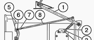
Wear of brake drums, brake bands and parts of the steering control drive makes it difficult to control the tractor. This wear is accelerated when there is little free play in the steering levers. Too much free play leads to insufficient tightening of the brakes, which makes it difficult to turn the tractor and increases wear on the rubbing surfaces of the brakes due to their strong heating. Therefore, every 240 hours of tractor operation, the turning mechanism should be checked and, if necessary, adjusted. The planetary rotation mechanism is adjusted in the following order: remove the hatch covers in the rear wall of the rear axle housing. The two outer hatches are designed for access to the adjusting nuts of the carrier brakes, and the two inner hatches are for the adjusting nuts of the sun gears; using adjusting nuts 11 (Fig. 66), tighten the bands 13 on the brake drums 12 of the sun gears until they stop, and then unscrew the nuts until the marks on the rods 10 align with the plane of the lugs; Having unscrewed the lock nuts, screw in the adjusting screws located in the lower part of the crankcase until they stop, and then unscrew them one turn and lock them with the nuts;
by screwing or screwing the forks on the rods, they regulate the free play of the turning levers, which should be within 60-80 mm. Both levers must be in the same plane; install the tooth of the right brake pedal 2 (see Fig. 2) into the second cavity of the retainer; tighten the brake band with adjusting nut 5 (Fig. 66) so that it fits tightly to the surface of the right brake drum; align the other pedal with the pedal locked with the clamp, and tighten the brake band of the left drum with the adjusting nut; Using the adjusting screw, set the gap between the bottom of the brake band and the drum, screwing the screw all the way and unscrewing it one turn. Upon completion of the adjustment, the full travel of the stopping brake pedals should be within 120-140 mm.
Source
Dt 75 clutch all adjustments
Tractor DT-75M. Adjusting the tractor control mechanism
Reliable and durable operation of the tractor transmission largely depends on the correct and timely adjustment of the control mechanism of its units. Due to the fact that in the first 100-200 hours of tractor operation the brake linings and friction clutch discs are intensively worn in, during this period the adjustments of the tractor control mechanism are often disrupted.
Adjustment operations associated with natural wear during operation are described in the section “Operational adjustments of the tractor control mechanism.”
In addition, there is a need to carry out a number of adjustment operations to ensure the correct interaction of individual transmission units and select the length of the control rods after repairing the tractor.
These additional adjustments are described in the “Recommendations for assembling the tractor control mechanism” section.
Tractor DT-75M. Operational adjustment of the tractor control mechanism without a torque multiplier
It should be remembered that the final stage of any adjustment operation is reliable fixation (with locknuts, cotter pins, etc.) of the corresponding adjustment elements. The reliability of operation of individual transmission units and the safety of tractor movement largely depend on this.
Adjust the tractor control mechanism in the following sequence:
1. Check and, if necessary, adjust the main clutch as described in the “Adjusting the Main Clutch” section.
2. Check and, if necessary, adjust the cardan brake (Fig. 90), as indicated in paragraph 6e of the “Main clutch control mechanism” section.
Rice. 90. Tractor DT-75M. Cardan brake adjustment: 1.10 - thrust; 2— emphasis; 3 - lever; 4 - pedal; 5 — drive lever; 6 — release clutch; 7 — cardan brake control lever; 8 — thrust bolt; 9— lever;
It is not recommended to allow gap A, which decreases as the cardan brake lining wears, to be less than 0.5-1 mm.
When using all the threads of the thrust bolt 8, it is allowed to rearrange the lever 7 on the splines of the shaft.
3. Check and, if necessary, adjust the travel of the stopping brake pedals.
The stroke of the right pedal 2 (Fig. 91) is considered to be adjusted correctly if, when it moves from the vertical position to full forward, tooth 4 is installed in the cavity “B” of sector 5 and at the same time the stop brake pulley is tightened with tape. Pedal travel increases as the brake pads wear out.
The pedal stroke should not be allowed to increase to such an extent that tooth 4, with the stopping brake band fully tightened, is not installed in the cavity “A” of sector 5, but moves further forward.
To restore pedal travel, do the following:
a) remove the covers of the two outer adjustment hatches located on the rear wall of the transmission housing;
b) install tooth 4 of the right pedal into cavity “B” of sector 5;
c) tighten nut 11 completely, tightening the brake band
Adjust the travel of the left pedal 1, which does not have a sector, in the same sequence, with the right pedal, the tooth 4 of which is installed in the cavity “B” of sector 5, serving as a guide.
4. Check and, if necessary, adjust the free play of the control levers.
Rice. 91. Tractor DT-75M. Adjusting the travel of the stopping brake pedals and their rods:
1 — left pedal; 2 — right pedal; 3 - lever; 4 — pedal tooth; 5 — sector of the right brake pedal; 6 — fork: 7 — traction; 8 — stopping brake pulley; 9 — brake band; 10 — adjusting screw. 11 — adjusting nut; 12 — brake lever; 13 - thrust
The free play, measured at the ends of levers 2 and 3 (Fig. 92), should be in the range of 80-100 mm.
As the brake linings of the planetary turning mechanisms wear out, the free play of the levers decreases.
Be sure to check the free play of levers 2 and 3 while the tractor is moving and do not allow it to decrease to less than 20 mm.
Adjust the free play of the levers when the belt linings are worn in to the pulley in the following sequence: , *
Adjusting the control mechanism
Premature failure of power transmission mechanisms can occur as a result of improper adjustment of the control mechanism.
Before making adjustments, you must first make sure that the power transmission mechanisms are correctly adjusted and, if necessary, adjust them.
Adjusting the brake control mechanism of the planetary mechanism of the rear axle consists of setting the free play of the control levers within 6080 mm by changing the length of rods 4 (Fig. 70) and 44 after the brakes are adjusted.
The length of the rod 44 is changed by rotating the threaded coupling 32, and the rod 4 by screwing or unscrewing the fork of the front end of this rod.
The rear axle stopping brake control mechanism is adjusted by changing the length of rods 3 and 43 so that the stopping brake control pedals 12 and 14 are in a vertical position when the rear axle stopping brakes are fully released.
Before changing the length of the rods 3 and 43, it is necessary to slightly loosen the adjusting nuts of the stopping brakes, and push the rods back by hand so that the fingers 42 (Fig. 65, b) and 43 of the double-arm levers 34 touch the bottom of the depressions of the brake brackets. The length of rods 3 (Fig. 70) and 43 is adjusted by screwing the forks onto the front ends of these rods or screwing them together. After both pedals are installed vertically, by screwing the adjusting nut of the right stopping brake, set the travel of the right pedal so that when the right stopping brake is fully tightened, the pedal tooth is fixed in the first cavity of sector 15. Using the adjusting nut of the left stopping brake, set the travel of the left pedal so that when when the brake was applied, it coincided with the right one.
The control mechanism of the main clutch, the UKM clutch, the blocking of these clutches, the UKM carrier brake, the servomechanism and the gearshift mechanism locking are adjusted by changing the length of the control rods of these mechanisms.
The length of the rods connected to lever 9 of the main clutch is set so that at the moment when the main clutch is completely disengaged, the UCM clutch is also disengaged, the UCM carrier is braked and the gearbox shift mechanism lock is fully opened.
These rods are adjusted in the following order.
1. Check and, if necessary, adjust the main clutch and the UKM clutch.
For the main clutch, the gap between the end of each release lever and the end of the release clutch sleeve should be 3 ± 0.5 mm. For the UKM clutch, the gap between the offset bearing and the pressure levers is 4 ± 0.3 mm. In this case, the difference in clearance for individual levers of one coupling should not exceed 0.3 mm (Fig. 71 and 72, a).
2. Set the release stroke of clutch 8 (Fig. 71) so that the main clutch is completely disengaged.
To do this, set the lever 10 of the main clutch release clutch back 40 ±5° from the vertical position. In this case, the release clutch 8 should occupy the rearmost position, i.e., be pressed against the housing 7 of the rear bearing of the main clutch shaft. Without changing the position of the lever 10, adjust the length of the rod 3 by rotating the threaded coupling 2 so that the upper arm of the lever 4 is tilted back by 3040°, and when this lever moves forward until it comes into contact with the stop, the release clutch 8 moves forward by 22 + + 4 mm . If the release clutch travel is insufficient, rod 3 should be shortened.
3. Adjust the length of the rod 1 of the servomechanism so that when the lever 4 is retracted to the rearmost position, when the clutch 8 for disengaging the main clutch is pressed against the bearing housing 7, the double-arm lever 12 does not reach the stop // by 12 mm (gap B in the figure 71). Then tension the spring 5 of the servomechanism with the adjusting screw b so that the lever 4 is fixed in the front and rear positions.