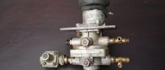
Spare part trailer brake control valve with two-wire drive MAZ, KamAZ
Purpose: Designed to control the brake system of a trailer with a two-wire drive. If the control brake line of a trailer breaks, the compressed air supplied from the vehicle to the trailer is blocked, with a simultaneous reduction in the pressure of the supply line. Available in two versions. A design feature of version 6024.35.22.010-10 is the installed muffler* 8088.00.00.000 TU RB 100185185.060-2001, designed to reduce the noise level when releasing compressed air into the atmosphere.
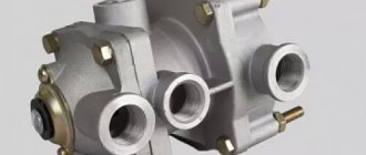
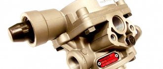
Description of operation: The supply line from the tractor receiver is connected to terminal 11 of the valve (Fig. 1), and the supply line of the two-wire trailer drive is connected to terminal 12. Pin 22 is connected to the control line of the two-wire drive, pins 41 and 42 are supplied with compressed air from both sections of the brake valve (that is, from the drive circuits of the tractor's service brake system), and pin 43 is connected to the manual reverse-acting brake valve (that is, with drive of the spare and parking brake systems). Pin 3 is atmospheric. When the vehicle is disengaged, compressed air from the tractor's receiver passes through terminal 11 to terminal 12 and then into the supply line of the trailer. Compressed air entering port 43 from the reverse-acting manual brake valve holds the middle piston 6 in its lowest position. When braking by the vehicle's working brake system, compressed air enters terminals 41 and 42. Pistons 8 and 9 move down, valve 5 opens and the trailer brake control line connected to terminal 22 is filled with compressed air. The pressure increase in terminal 22 continues until the pressure from below on pistons 8 and 9 will not balance the pressure coming from pin 41 on these pistons from above. An equilibrium position arises. In this way, a tracking action is carried out. When the brakes are released, the pressure in ports 41 and 42 decreases and pistons 8 and 9 move upward, closing valve 5. Air is released from port 22 into the atmosphere through port 3. When braking with the parking or emergency brake system, air is released from port 43. Piston 6 rises up to the stop against the piston seat 9. Valve 5 opens and the trailer brake control line is filled. The tracking action is achieved by balancing the pressure of compressed air from below on piston 6 and the sum of pressures from above on piston 6 and diaphragm 13. If the control line is damaged or depressurized, the pressure in cavity A begins to drop during braking, piston 10, under the influence of pressure in cavity B, moves down and shuts off supply line connected to terminal 11. As a result, the pressure in terminal 12 also begins to drop, since air from the trailer supply line connected to terminal 12 escapes into the atmosphere through damage to the control line. The trailer quickly self-brakes.
Technical characteristics: Operating pressure MPa 0.8 Sensitivity to control pressure from the brake valve MPa no more than 0.03 Sensitivity to control pressure from the parking brake valve MPa no more than 0.05 Operating temperature values during operation. C from minus 45 to plus 80 Connecting threads M16* 1.5-bN Overall dimensions, mm. no more than 135x169x75 135x169x208 Weight, no more. kg 2.2 2.27 * For the version with a silencer, the sound level is no more than 95 dB|A|, which corresponds to a sound level of no more than 72 dB(A).
A standard trailer brake control valve is used to control the brakes of a semi-trailer when a similar system on a tractor is activated. In addition, it is responsible for automatically applying the brakes in the event of a critical drop in pressure in the line. The drive of this unit is of a combined type (one and two wire). Let's look at the design features, design and connection of the device.
Short description
The trailer brake control valve consists of the following elements:
- Pair control valve and similar single element.
- Two isolation valves.
- A pair of connection heads.
The valve is responsible for controlling the brakes of the semi-trailer, directing compressed air from the input source to subsequent consumers, working both synchronously and separately. A command is sent to two outputs to increase the pressure in the line, and one analogue receives the opposite action, affecting a decrease in pressure when releasing the air mixture using a hand lever.
Device
The brake system circuit is designed on the principle of independent influence on the drive mechanisms of the wheels of the front and rear axles. The pneumatic vehicle used on MAZ vehicles consists of the following elements:
- compressor;
- compressed air tanks (receivers);
- pneumatic pipelines and control devices;
- brake mechanisms.
The vehicle can be equipped with a single or double cylinder compressor. The latter is used on tractors (road trains).
Compressed air is supplied through a pneumatic line to the receivers. Depending on the model, the vehicle can use 3 or 4 air cylinders of different capacities. Each pair of wheels (axle) has its own receiver: front and middle - 40 liters each, rear - 20 liters. The parking system is equipped with a separate 20-liter cylinder.
The design of the MAZ brake system provides for the installation of drum-type brakes.
Here, braking occurs due to friction arising from the contact of the pads located on a stationary caliper to the inner surface of the movable (rotating) drum. It is made of cast iron with a diameter of 420 mm and a working surface width of 160 mm.
The brake pads are made of steel. Friction linings made of asbestos-free material are installed on top. The gap between the pads and the surface of the drum is adjusted by a lever with a built-in automatic adjuster. The front wheel brakes are actuated by diaphragm brake chambers (BC). On the rear axles, the force on the pads is transmitted by spring energy accumulators.
Control air is supplied to the actuators by the brake valve through a four-circuit valve. This applies the brakes on all wheels simultaneously. If there is a trailer, to prevent it from hitting the tractor, a trailer brake control valve is installed, which allows the brakes to be applied slightly faster than on the tractor.
Control valve
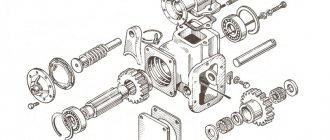
The trailer brake control valve is equipped with a main valve, which consists of three sections, a large and small piston with springs. The middle piston element has an inlet valve that presses the spring against the seat.
The remaining components of the part in question:
- Diaphragm.
- Discharge hole.
- Stock.
- Adjustment screw.
In the released position, compressed air is constantly supplied to the output parts. It acts on the diaphragm and piston, holding it together with the rod in the lower position. This is facilitated by the increased diaphragm area. At the top, the piston group is located in the uppermost position, and the exhaust valve is separated from the seat. The inlet analogue is in a closed state under the influence of a spring. One of the leads connects the brake control line to the atmospheric outlet using relief holes and a rod.
Valve operation during braking
The valve of the KamAZ trailer brake control valve supplies compressed air from the sections of the device to the terminals when braking. From the other outlet of the air tank, the compressed mixture flows to the control terminal, after which it is sent to the main part. There, the air acts on the piston until it is balanced at the bottom under the upper pressure. The upper piston operates under the force of air pressure and spring. In this case, the middle piston must also be balanced under the influence of identical factors. In principle, a general tracking action occurs.
When the brakes are released, compressed air is discharged through the atmospheric opening of the valve from the filled compartments. The pistons, under the pressure of the spring and the air mixture, move to the upper position, and the rod with the piston moves down. The valve comes off the seat and connects the internal and external inlet.
Suitable compressed air causes the rod and piston to move separately upward, and the large and small piston element downward. Subsequent operation of the brakes follows a similar principle.
When the truck's backup or parking system is activated, compressed air is drawn through the atmospheric port in the manual return valve and released to the outside. The degree of pressure above the diaphragm decreases, reducing the force on the working elements. The seat rests on the valve, separating the outlet from the atmosphere. Then the valve opens, communicating between the outlet and the main line.
Repair of reverse acting brake valve
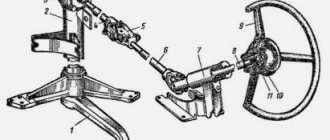
The manually operated reverse-acting brake valve (Fig. 277) is disassembled during repairs in the following sequence:
- unscrew the fastening screws and remove cover 3 assembled with the handle;
- remove spring 2;
- lifting the rod 12, remove the pin, remove the washer and cap 8 of the guide;
- compressing the springs, remove the thrust ring, remove the rod assembly with guide 9 and spring 10;
- remove the piston 13 assembly, disassemble it by removing the thrust ring;
- remove the spring, support washer, valve 1 and valve ring.
After disassembling, the faucet parts should be degreased and washed in hot water.
The crane is assembled in the reverse order of disassembly, under conditions that prevent the ingress of dust and dirt. All rubbing surfaces of parts and assemblies must be lubricated with a thin layer of CIATIM-221 lubricant. Rubber parts must not be damaged.
If the force of spring 1 (Fig. 278) with a stroke of 0.5 mm in the direction of arrow A is less than 0.26 N (2.6 kgf), you need to install a washer. One washer gives an increase in spring elasticity of 0.42 N (4.2 kgf) [pressure drop of 0.035 MPa (0.35 kgf/cm2)], which corresponds to a deflection of the valve lever of 3.75°. After installing the thrust ring 3, the guide 5 must be pressed tightly against it, otherwise the spring must be replaced.
The gap x should not exceed 0.2 mm. Its value is set using washers with a thickness of 0.15, 0.2 and 0.3 mm, while washer 6 with a thickness of 0.5 mm should remain at the bottom.
Source
Peculiarities
In the trailer brake control valve, the main pressure is built up until the force acting on the piston from below is equal to the force applied to the diaphragm. This ensures follow-up operation of the valve.
When the compressed air mixture simultaneously approaches the working terminals, and the pressure in the compartment connected to the main line, and the pressure value exceeds the same value in the control terminal (20-100 kPa), the brakes act proactively. The required pressure value is adjusted using the adjusting screw by tightening or unscrewing it.
Disassembly and assembly of MAZ brake valve
The brake valve (Fig. 283), removed from the car for repairs, is disassembled in the following order:
- unscrew the bolts and remove the support plate 32 together with the body 7 and lever 1;
- remove pusher 6;
- remove the upper piston 30 with the balancing element assembly;
- remove spring 12;
- unscrew the bolts and disconnect the upper 33 and lower 25 housings;
- remove the large 28 and small 15 pistons assemblies;
- remove the small piston from the large one;
- remove spring 26;
- remove the retaining ring 22 and remove the seal, support ring, spring 24 and body with valve 17;
- remove the retaining ring and take out the outlet window, support ring and valve 29 of the upper section assembly;
- remove lever 1 of the brake valve, for which remove the axle.
After complete disassembly, the brake valve parts should be degreased and washed in clean hot water.
The brake valve is assembled in the reverse order of disassembly, under conditions that prevent dust and dirt from getting on the parts. During the assembly process, to ensure trouble-free operation of the crane, the following must be done:
- Lubricate all rubbing surfaces of the valve parts and components with a thin layer of CIATIM-221 lubricant;
- Install valves, rings and other rubber parts carefully to prevent damage. There should be no cuts or marks on the surfaces of rubber parts;
- when installing the upper piston, measure the distance c (Fig. 284) - the protrusion of the shank of the small piston above the valve. Using the adjusting screw on the upper piston, set the distance d = c + 0.8 mm;
- install the upper piston 30 (Fig. 283);
- assemble the crane with base plate 32 and lever 1;
- put on the protective cover 3.
Source
Isolation valve
This part is involved in the operation of the trailer brake control valve as follows:
- If necessary, it closes the pneumatic line connecting the tractor with the towbar.
- If you install the handle of the device along the axis of the valve, the pusher with the rod will be in the lower position and the valve will be open. Air in a compressed state through it and the corresponding outlet is directed from the car to the semi-trailer.
- When the handle is placed across the frame, the rod and diaphragm move upward under the influence of air pressure and spring. The valve blocks the leads by sitting in the seat. The air mixture flows from the connecting system into the atmosphere, which makes it possible to disconnect the connecting heads.
Below is a schematic representation of the crane, as well as the main symbols and components.
- a – the device is not active;
- b - position of the open tap;
- 1—output to the tractor air cylinder control valve through a single safety valve;
- II - Main outlet of the trailer brake system;
- III - atmospheric output;
- 1 - spring mechanism;
- 2 - valve;
- 3 — diaphragm with rod;
- 4 — return spring;
- 5 - pusher with handle.
Adjustment
In serviceable and adjusted brakes, the gap between the lining and the inner surface of the drum should not exceed 0.4 mm. This corresponds to the movement of the TC rod by 25-40 mm. If this value increases to 45 mm or more, then adjustment of the brakes is necessary. Most drivers prefer to do this work with their own hands.
Adjustment work involves sequentially performing the following actions:
- placing the axle on a jack;
- releasing the worm screw of the adjusting lever from the locking plate;
- turning it until the rotating wheel begins to brake;
- rotation of the worm in the opposite direction by 1/3 of a turn, which will correspond to a rod stroke of 25-40 mm.
- return the stopper to its original position.
It must be remembered that the difference in stroke of the TC rod on one axis should not be more than 8 mm. Serviceable brake systems will ensure safe movement and parking of the car.
In this article we will talk about the design, as well as the features of servicing components. So, the brakes of the MAZ semi-trailer are divided into two systems: working and parking. Both mechanisms act on elements in the form of pads.
The parking brake operates mechanically.
The pneumatic drive of the system operates on a single-wire principle and starts after pressing the pedal.
Single wire system
Unlike the two-wire trailer brake control valve, this design consists of a control valve, a disconnecting analogue and an L-shaped connecting head.
The single-line actuator brake control valve operates through a single line that serves as a supply and control system. It is worth noting that the valve functions to reduce pressure in the main line, with the ability to bring the indicator to the atmospheric parameter. As the pressure decreases, the intensity of the towbar braking increases. Other parts of the valve include: pusher with diaphragm, step type piston, valves (inlet and outlet). They are aggregated between themselves by means of a connecting rod. There is also a lower piston.
Working in a disinhibited state
In the inactive position, air in compressed form flows from the parking brake system cylinder to the outlet, which is connected to the atmosphere via a control valve. Under the influence of the power spring, the diaphragm and pusher are located in the lower position. The exhaust valve remains closed, while the intake valve operates open, allowing air to flow to an outlet that connects to the single-line brake control line.
Synchronously compressed air is supplied to special cavities, the pressure in which remains equal. Taking into account the fact that the area of the stepped piston is larger, it moves upward until it stops. When the pressure in the trailer brake line chamber reaches about 500-520 Pa, the lower piston goes down and blocks the inlet valve. When the brakes are released, the system automatically maintains a pressure level of 500 Pa, which is slightly lower than the same parameter in the pneumatic drive of a truck.
content .. 61 62 64 ..Trailer brake control valve with single-wire drive for MAZ-64227, MA3-54322 vehicles
(Fig. 103). Designed to control a single-wire system of pneumatic drive of semi-trailer brakes.
Rice. 103. Brake control valve for a semi-trailer with a single-line drive: 1 - top cover; 2. 12, 18 — springs; 3 — protective cap; 4 — small diaphragm washer; 5 — large diaphragm washer; 6 - diaphragm; 7 - bolt; 8 — valve body; 9 - piston; 10 — valve pusher; 11 - valve; 13 — bottom cover; 14 - screw; 15 - nut; 16 — spring plate; 17— valve; 19 - cover; - 1, II,
III
- conclusions;
A, B, C - cavities In the initial position (brake pedal released), compressed air is supplied from the air cylinder to terminal II, terminal I
connected to the atmosphere through the brake valve.
In this case, under the action of the power spring 2, the diaphragm 6 with the pusher 10 is in the lower position. The outlet window is closed by the pusher seat, terminal III
is disconnected from the atmosphere. The valve stem is moved to the lower position and torn away from the valve seat I, the inlet window is open, terminal II is connected to terminal III. Compressed air from outlet II passes through the open inlet window of the valve to outlet III and then into the connecting line for controlling the brakes of a single-line drive semi-trailer.
At the same time, compressed air enters cavities “B” and “C”. The pressure in them is the same, however, due to the fact that the piston area
9, which is affected by the pressure of compressed air in cavity “B”, which is greater than in cavity “B”, the piston moves up until it stops against the cover 19.
When the pressure in the semi-trailer line reaches 5.0-5.2 kgf/cm2, valve seat 11
under the influence of this pressure, it moves down, compressing spring 12. closes the inlet window and stops the supply of compressed air to the brake line.
When the pressure in the brake line decreases below the specified limits of 5-5.2 kgf/cm2, the valve seat, under the action of spring 12, moves upward and reopens the inlet window.
When the vehicle is braking, compressed air from the brake valve is supplied to the brake chambers and to output I of the brake control valve of a semi-trailer with a single-wire drive.
Compressed air from outlet I through the hole in the housing, filling the cavity “L”, acts on the diaphragm 6, which has a large area, and moves the pusher 10 upward, overcoming the resistance of the spring 2. When the pusher moves up, the valve stem 17 under the action of the spring 18 is pressed against the seat pusher 10 until it rests against valve seat 11 and closes the inlet window, thereby disconnecting terminal II from terminal III. With further movement of the pusher, its seat breaks away from the valve stem 11, opens the outlet window, communicating pin III with the atmosphere. Compressed air escapes into the atmosphere through a hollow pusher and a hole in the top cover. The tracking action is carried out by piston 9.
When the pressure in cavity B decreases due to an increase in pressure in cavity A (the pressure in cavity B remains the same), the piston begins to perceive force from the pressure in cavity A. Under the influence of the pressure difference, the piston begins to move down, moving the pusher, the seat of which closes the outlet window.
A further increase in pressure in port I leads to the complete release of air from the brake line of the semi-trailer and thereby to its complete braking. In this case, the pusher
10 is in the uppermost position, the outlet window is open, the inlet window is closed. The piston 9 is pressed against the cover 19 by the thrust ring of the pusher.
When the car is braked, terminal I communicates with the atmosphere through the hole in the brake valve. The pressure in cavity A drops. The pusher 10 with the power spring 2 moves downward under the force transmitted by the piston from the pressure in cavity B. The pusher seat rests on the valve stem 17 and closes the outlet window, disconnecting terminal III from the atmosphere. With further movement of the pusher, the spring 18 is compressed, the valve 17 comes off the valve seat 11, connecting terminal II with terminal III. Compressed air enters the brake line of the semi-trailer. The valve returns to its original position.
Auxiliary brake system valve for MAZ-64227, MA3-54322 vehicles
Designed to control the auxiliary brake system cylinder.
When you press button 1 (Fig. 104), the pusher 18 moves inside the sleeve 17 and sits with its end on the valve 7, disconnecting the output / from the atmospheric outlet III. With further movement of the pusher, the valve is pressed away from the body seat, thereby opening the passage
compressed air from terminal II to terminal I and then into the actuator line.
When the button is released, the pusher returns to the upper position under the action of spring 14. Valve 7 closes the hole in plate 4, stopping the flow of compressed air into terminal I, and the hole in pusher 18 opens, connecting terminal I with atmospheric terminal III. The compressed air in the actuator line exits into the atmosphere through holes A in the pusher and outlet III.
Rice. 104. Auxiliary brake system valve;
content .. 61 62 64 ..
How does the system function when braking?
When the tractor brakes are activated, compressed air from the double-circuit valve flows to the valve of the single-line valve for controlling the brakes of the MAZ trailer. The mixture fills the plane under the diaphragm. After overcoming the spring force, the diaphragm moves upward along with the pusher, the intake valve closes, and the exhaust element opens. The air escapes into the atmosphere, bypassing a special outlet, a pusher and a hole in the cover.
The stepped piston performs a follower action. If the pressure at the outlet and in the cavity decreases, the force on the piston from below also decreases. In the upper part, this element is subjected to pressure from the corresponding cavity, identical to the force in the second compartment. The hub, in turn, receives force from the first cavity. As a result, due to the pressure difference, the piston moves downward, dragging with it the pusher, which closes the outlet window with its seat. The subsequent increase in pressure causes the complete release of the air mixture from the main brake structure of the semi-trailer. The pusher is in the lowest position, the inlet window is blocked, and the outlet element is open.
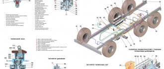
Design of the brake system of a MAZ semi-trailer
- Connecting node;
- Moisture distributor;
- Manually controlled crane rods;
- The crane itself;
- Air distributor;
- Air cylinders;
- Brake chambers.
The task of cleaning the air in the brake drive is solved by a moisture-oil separator. Air purified from water vapor and oil particles is sent to the pneumatic system.
The mechanism is located in front of the valve assembly in the supply pipeline.
The impellers are fixed to the housing through spacer bushings and coupling bolts. The MAZ semi-trailer valve is responsible for draining the condensate. All components are very strong and durable.
However, if you need to replace a faucet or water-oil separator, our website contains MAZ spare parts in a catalog by group.
Variable mode
Connecting the trailer brake control valve implies normal operation of all components of the device. The single-wire version, when the tractor brakes are released, interacts with the atmosphere through the provided opening of the two-wire drive valve. The pressure in the working cavity decreases, and the diaphragm with the pusher moves to its original position, blocking the outlet valve and opening the inlet element. The compressed air enters the terminal and connecting system of the trailer, releasing it.
The L-shaped coupling head aggregates with the single-wire drive line, automatically closing the truck's coupling system in the event of spontaneous disconnection of the heads, which can happen when uncoupling a trailer. The head is equipped with a valve, locked by spring action in the disconnected element, and opened in the connected head by means of a pin.
Wabco Trailer Brake Control Valve
It is these structures that are equipped with trailers connected to MAN, DAF, and Volvo vehicles. There are several modifications of cranes. Let's consider the features of the unit with the ability to set advance.
The working braking of the unit consists of supplying air through the connection head. Power passes through the tap outlet to the semi-trailer receiver. Synchronously, the piston, under spring pressure, moves down along with the valve. Opening the outlet that connects to the working leads. After the tractor brakes are activated, the compressed air mixture flows through the connecting head into the piston chamber.
After closing the outlet, the MAN trailer brake control valve supplies air from the receiver through the outlets to the cylinders. At the same time, the mixture enters a special chamber and creates a force on the valve. After the maximum pressure is built up, the valve opens to meet the compression of the spring. As a result, air enters the storage compartment, loading the lower part of the piston. After the summed pressure in all chambers reaches the set limit, the piston moves upward.
Automatic braking
When the supply line ruptures, the Volvo trailer brake control valve receives a sharp drop in pressure, as a result of which the load on the piston is removed. Under the force of the spring, the piston moves upward, and the valve closes the outlet. The piston part with further movement releases the inlet window.
Through the outlets, the pressure from the receivers is fully supplied to the brake cylinders. If the line breaks, the DAF trailer brake control valve operates according to a similar scheme as described above. This is due to the fact that the pressure in the supply structure of the crane also decreases due to leakage of the unit after the tractor starts braking.
Malfunctions
There are a number of problems that can reduce the effectiveness of your brakes. A trailer brake control valve repair kit may be needed in the following cases:
- After disconnecting the heads in the main line and opening the isolation valve, air from it does not flow to the tractor.
- When the disconnect valve is open, the air mixture flows from the head into the tractor line, but after connecting the elements of the tractor and the trailer distributor, the flow stops.
- When the brakes are activated, the brakes on the vehicle work, but the brakes on the semi-trailer do not.
- In the case when air comes out of the head during braking.
- During the release of the brakes, the wheels of the tractor react, but remain in a braked state on the towbar.
Devices for multi-circuit pneumatic brake drive
Trailer brake controls
The brake drive of a trailer can be two-wire or single-wire, depending on the number of circuits designed to supply the pneumatic drive with air and control the braking processes of the trailer. Therefore, to connect to the pneumatic drive of trailers, valves for two-wire or single-wire drives of different designs can be used.
Modern trailed vehicles are often equipped with two-wire drives, which have two lines and provide reliable control of the trailer brakes. However, the single-line drive is also widely used in the braking systems of trailers and semi-trailers due to its simplicity and the ability to automatically brake the trailer in the event of separation from the tractor.
For these reasons, tractor-trailer vehicles are typically equipped with both types of control valves, as well as corresponding coupling heads, to allow connection to a trailer with any air drive configuration. The main role in controlling the trailer brakes is played by the combined air distributor.
Combined air distributor
The combined trailer air distributor allows the trailer to be used with towing vehicles that have a single-wire or a two-wire drive to the trailer. The supply line is connected to terminal II. The control line is connected to pin III. Pin IV is connected to the brake chambers, and pin I is connected to the trailer receiver.
When the brake pedal is released, compressed air is supplied through the supply line to terminal II and through cavity B under piston 8. Then, bending around the edges of the piston collar 8, the air enters cavity A and through channel 6 and terminal I into the trailer receiver. The brake chambers are connected to the environment through terminal IV, open inlet valve and terminal V.
When braking, compressed air is supplied through the control line to terminal III and, passing through the channel into the cavity above piston 5, lowers it down. The exhaust valve 16 closes, and the inlet valve 3 opens, and compressed air from the receiver through terminals I and IV through channel a and the open valve 3 enters the brake chambers. Air will flow in until the pressure acting on piston 5 from below and above is balanced. After which both valves 3 and 16 will close. In this way, a tracking action is carried out.
If the trailer is separated from the tractor, compressed air from the connecting supply line escapes into the environment, and the pressure in port II and in cavity B drops sharply. This leads to the lowering of piston 8 under the influence of pressure in cavity A and the opening of inlet valve 3, through which air from the receiver begins to flow into the brake chambers, performing emergency braking of the trailer.
To release the trailer, you need to pull the release valve rod 14 by the handle. Air from the brake chambers will escape into the environment, and the trailer will release the brakes. The trailer is braked by returning the release valve handle to its original position.
When connecting a trailer to a tractor with a single-line drive of the trailer brakes, only one terminal II is used in the air distributor. In this case, filling the receiver occurs in the same way as in a two-wire drive. Braking occurs as a result of the release of air from the connecting line through the brake valve of the towing vehicle. This leads to a decrease in pressure in cavity B and under piston 8, as a result of which it lowers, closing the exhaust valve 16 and opening the inlet valve 3. Compressed air from the receiver through terminals I and IV begins to flow to the brake chambers, as a result of which the trailer is braked.
Two-wire trailer brake control valve
The two-wire actuator includes a two-wire trailer brake control valve (Fig. 1), a single safety valve, two isolation valves and two Palm connection heads.
The control valve is used to control the brake mechanisms of the trailer under the action of three independent circuits simultaneously or separately: the drive of the brake mechanisms of the service brake system of the front wheels, the drive of the brake mechanisms of the service brake system of the wheels of the rear bogie, as well as the drive of the brake mechanisms of the parking and spare brake systems. When the first two circuits are operating, a direct-acting signal is sent to the valve (i.e., increased air pressure); when the third circuit is operating, a reverse-acting signal is supplied (i.e., reduced pressure when air is released by the parking and spare brake system control valve). In all cases, the control valve directs compressed air from the receiver to the brake chambers of the trailer wheels during braking and releases air from them into the environment when the brakes are released.
The control valve consists of three parts. The upper section of the valve contains a two-section piston with a spring, a follower piston with a spring and an adjusting screw. The bottom of the piston forms the exhaust valve. The middle section contains a piston with a spring, an inlet valve with a relief hole inside and a rod fixed in the membrane.
In the disengaged state, air is not supplied to the terminals of the upper and lower sections from the two-section brake valve. Compressed air is supplied to the outlet of the control valve for the brake mechanisms of the parking brake system, which acts from above on the membrane. At the same time, compressed air acts on the piston from below, entering through the outlet from the receiver. Due to the fact that the diaphragm area is larger than the piston area, the diaphragm together with the rod is in the lower position. The two-section and follower pistons are in the upper position under the action of a spring. The exhaust valve extends from the intake valve, which remains closed under the action of its spring.
The cavity above the piston, and, consequently, the outlet to the trailer brake line and the trailer brake control line is connected through the opened relief hole to the outlet to the environment.
In the case of braking by the service brake system (two circuits), compressed air from the lower and upper sections of the two-section brake valve is supplied to the corresponding terminals on the control valve. The exhaust valve is pressed against the intake valve and, closing its internal hole, disconnects the trailer brake line outlet from the environment, and upon further movement, overcoming the resistance of the spring, it separates the intake valve from the piston.
Compressed air from the receiver flows through the opened inlet valve into the brake line and then into the trailer brake control line. Compressed air will flow until equilibrium is achieved: in the upper section - between the air pressure on the follower piston from below and the air pressure and balancing spring on the same piston from above; in the middle and lower sections - between the compressed air pressure on the piston from above and the air pressure acting on the membrane from below. Thus, a tracking action is carried out.
6.3.4. Brake systems. Pneumatic drive. Trailer brake control valve. Repair
Repair of two-wire trailer brake control valve. To remove the valve (see Fig. 108), disconnect the pipelines and unscrew the nuts of the mounting bolts.
Disassembling the valve should be done in the following sequence: · unscrew the nuts of the bolts securing the upper housing, remove the upper housing 1, remove the spring 14, remove the upper large piston 3 assembled with the small piston 4; · unscrew the bolts 6 and disconnect the lower 8 and middle 2 housings; · holding the lower piston 9 from turning, unscrew the nut and remove the washers and diaphragm 7, remove the middle piston 11 assembly; · remove the thrust ring, remove and disassemble the upper small piston; · remove the thrust ring, remove valve 5 and spring 10; · Unscrew the screws and remove the outlet window. The valve is assembled in the reverse order of disassembly, under conditions that prevent the ingress of dust and dirt. All rubbing surfaces of valve parts and assemblies must be lubricated with a thin layer of CIATIM-221 lubricant. Rubber parts must not be damaged. The operation of the valve is checked on a stand, the diagram of which is shown in Fig. 120 in the following sequence: · connect the valve according to the diagram, with tap 12 open and tap 6 closed; · set the pressure to 7 kgf/cm² according to the readings of pressure gauges 4 and 13; · quickly transfer the pressure twice according to the reading of pressure gauge 4 from 7 kgf/cm² to zero and back. In this case, the pressure value according to pressure gauge 9 should quickly increase and decrease accordingly; · check the valve for leaks by covering the place where air is released from it and stop valve 6 with soap emulsion; · slowly reduce the pressure on pressure gauge 4. In this case, the ratio according to the readings of pressure gauge 4 and 9 should correspond to stage 1 of Table 13.1;
· slowly increase the pressure on the pressure gauge 4. . In this case, the ratio according to pressure gauge readings 4 and 9 must correspond to stage 2 of table 13.1; · set the pressure on pressure gauge 4 to 7.0 kgf/cm²; · quickly transfer the pressure twice according to pressure gauge 3 from zero to 7.0 kgf/cm² and back. In this case, the pressure on pressure gauge 9 should quickly increase and decrease; · slowly increase the pressure on pressure gauge 3, while the ratio according to pressure gauge readings 3 and 9 should correspond to stage 3 of Table 13.1; · slowly reduce the pressure on pressure gauge 3, while the ratio according to pressure gauge readings 3 and 9 should correspond to stage 4 of Table 13.1; · open shut-off valve 6. Slowly increase the pressure according to pressure gauge 5, while the ratio according to the reading of pressure gauge 5 and 9 should correspond to stage 5 of Table 13.1; · set the pressure to 7.0 kgf/cm² according to the reading of pressure gauge 3; · check the valve for leaks; · close shut-off valve 12, set the pressure to zero according to the readings of pressure gauges 3 and 5. The stepwise change in pressure during all tests should not exceed 0 3 kgf/cm².
Source