[contents]
Today we will tell you how to build a jib crane with your own hands. But first, a few words about how this design differs. So, jib cranes are used to lift moderate loads and are ideal for servicing construction sites. Moreover, they are also used in other areas of industry - mechanical engineering, machining shops, etc. Such a wide range of operation is explained by the possibility of working in wall conditions, that is, in limited space.
Types of jib crane
There are two types of such cranes.
Mobile structures consist of a frame resting on two wheels and moving along special guides. The console itself is attached to the frame.
Stationary structures are mounted on walls or special columns. It is typical that the column can be installed on the base of the building. At the same time, cranes come in one- and two-arm types (depending on the type of support), and also have different lifting capacities.
The project described is non-standard, but to implement it you will only need two assistants. The procedure begins with drawing up a project.
Attention! All elements are adjusted for CNC gas cutting, as this is the cheapest option.
Jib crane design
A jib crane consists of two elements: a truss (a vertical column - the load-bearing part of the structure) and the console itself. The console is a horizontal beam along which a trolley with a load-handling mechanism (for example, a hook) moves. The mechanism can be lowered and raised, and the trolley itself moves in a horizontal plane.
A system of cables and special mechanisms are responsible for the movement of the trolley. The crane itself, as a rule, takes up little space and can be easily disassembled and transported.
Areas of application
Jib cranes can be a more convenient replacement for bridge structures: instead of two vertical supports, they use only one column, which can be rotated in the other direction. You can use console cranes:
- in warehouses;
- in ports, airports and other logistics centers;
- at industrial facilities.
Often such a screen is used as part of industrial equipment, and not as a separate structure. It simplifies the transfer of certain loads from one area of the workshop to another.
Drafting
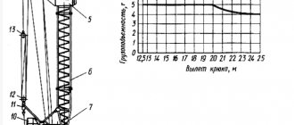
The crane will rest on three legs of a “twentieth” I-beam, secured with flanges made of 1.4-centimeter steel and M-16 bolts. A thick-walled pipe is used as a shaft. The legs are equipped with additional spacers.
The arrow will sag by 5 cm, since the legs have a small margin of safety (three are used instead of six). More details can be found here https://chelny-kran.ru/catalog/kran-balki-kontsevye-balki-krana/kran-konsolnyj.
Main components of the crane
The crane consists of the following main components:
- rotation bracket (1);
- console (2);
- column (3);
- traction chain (5);
- brackets (6 and 7);
- support washer (14);
- bearing support (15);
- nut (16);
- protective washer (17);
- hoist manual or electric (33).
- Dampers (pos. 32) 4 pieces are included in the design of the KKR-Ex crane (explosion-proof).
Main elements of a cantilever rotary stationary manual crane
| Manual console cranes on a column (type 3) are also manufactured in an explosion-proof design. Ex is added to the designation of an explosion-proof valve. Additional marking II Gb with T3 X. The photo shows an example of the marking on the tag of an explosion-proof cantilever crane with a lifting capacity of 500 kg, with a maximum hook reach of 2.5 meters, a lifting height of 4 meters, climatic version U1. | The column is a pipe that is welded to the base. The base is attached to the foundation with foundation bolts. The ribs provide rigidity to the structure. | ||
| KKR manual console cranes of explosion-proof design are equipped with rubber dampers - 4 pieces, installed on brackets. | Lifting, lowering and moving the load along the crane console is carried out using a manual or electric hoist. In particular, mobile manual hoists (TRShBp or TRShBK or TRShBM or TRShBMU) of appropriate load-carrying capacity can be used as a working body for KKR cranes. The photo shows a manual mobile gear hoist TRShBp-1.0. This hoist can be used as a working tool on KKR console cranes with a lifting capacity of 1 ton. | ||
| The crane can rotate 360 degrees. It is possible to limit the angle of rotation by installing stops. The photo shows the installation of stops that limit the angle of rotation of the crane boom to 270 degrees. The lugs available on the dimensional structural elements are intended for use during loading/unloading and installation of the crane. | The rotation bracket consists of: a plate for attaching the console; A bearing cup is welded to the plate, which is the connection point with the column. On the other hand, the rotation bracket rests on the column with thrust rollers attached to the plate. The plate is connected to the slab by cheeks reinforced with a channel. |
KKR jib cranes of all types are certified for compliance with the requirements of the Technical Regulations of the Customs Union TR CU 010/2011 “On the safety of machinery and equipment”.
The manual console crane KKR is shipped mothballed, disassembled. Large parts of the crane are supplied without packaging (rotation bracket, console, column). Components and parts are packaged and labeled.
The crane control system is manual. The control location during operation and during installation/testing is from the floor.
Assembly of the structure
For convenience, dig pits for the legs; carry out the assembly while lying down (this will take about a few hours). To lift the crane you will need a truck, a cable and a beam. Attach one end of the cable to the truck, the other to the crane. Using a truck, pull the cable through the beam until the structure stands on its feet.
Next, secure the boom and tighten the guy ropes. Actually, that’s all: the do-it-yourself console crane is almost ready! Of course, its construction requires a lot of effort, money and time, but soon it will fully justify itself. If everything is done correctly, then using a crane it will be possible, for example, to pour up to twelve cubic meters of concrete solution (with several assistants and a pair of concrete mixers). Good luck with your work!
Application area
The main part of the crane is the console. This is a beam located in the horizontal direction. A cart with a hook moves along it. The mechanism rises and lowers, and the trolley with the load moves only horizontally. If it is mounted on a wall, the mechanism is called a wall-mounted jib crane.
The cantilever beam is attached to a vertical column. Column-mounted jib cranes take up little space, are easily disassembled and transported to the desired part of the production area. They replaced bridge structures that stood on 2 supports and took up a lot of space on the site.
Console devices rotate around the column left and right, sometimes rotate 360°. Turns are carried out manually - the KKR is mechanical, or the turning mechanism can be equipped with a motor with a gearbox. The console uses a trolley that moves using cables.
Lifting mechanisms have found their application in warehouses, in the construction of household and industrial facilities, and at airports. Jib cranes are often used in production shops as additional equipment. With its help, heavy workpieces are moved to machines. In workshops it is also found standing on a column against the wall or in the middle part of the room.
If it is necessary to work with light loads, manually controlled structures are used - mechanical KKR. For heavy loads, there are console cranes of 2 tons, cranes with a lifting capacity of 5 tons, 10 tons and more. They are often equipped with electric traction and a hoist winch. To ensure greater stability, a cantilever double-arm crane unit is used.
Such equipment is produced upon individual orders. It can have a console of greater or lesser length, change the angle of rotation of the mechanism, the height of the load, and the load capacity of the device.
Jib crane drawing
In mechanical engineering, a turner is given the task of turning a simple bolt only in the form of a completed drawing on paper. By reading it, the master will make the part exactly according to the dimensions indicated in the drawings
Many wealthy organizations engaged in the production of marketable products have their own design departments, whose task is to design new types of products from scratch. These include machine-building enterprises specializing in the production of lifting machines. The client is ordered, for example, to manufacture a jib crane with the required lifting capacity for indoor workshop use or for outdoor work.
For this you need drawings of a jib crane. If the customer is able to provide them, this will significantly reduce the cost of producing the machine. But this rarely happens. What is the reason for even an economically powerful construction or any other company to form a staff of designers if the enterprise needs to purchase one of these lifting mechanisms in its lifetime. Of course, the company will turn directly to the product manufacturer or outsource this matter to technical outsourcing, so that they can produce drawings on their own, according to which the manufacturer will assemble the car.
And so, it all starts with the creation of drawings, according to which workers in production shops will manufacture the crane. It is believed that working on drawings is one of the most important mental processes in a design office. After all, this will require not only many sheets of whatman paper, but also all the parts and components that will create the mechanism from scratch must be made from the design material.
For example, a gearbox casing requires a certain grade of cast iron, a winch frame requires a certain grade of steel, and so on. And all their operational power parameters are tied to the designed load capacity of the lifting device and the temperature conditions of its operation. Subsequently, using the drawings of console mechanisms, machine-building enterprises will be able to supply especially advanced modifications to the serial flow.
Without creating dimensional drawings, it is difficult to release the ordered products from the factory. It is this type of graphical representation of the entire structural part of the crane that will help production workers accurately recreate the machine in the original. The master who supervises the production of products reads dimensional drawings well and will not allow technological deviations from the specified parameters.
They will tell him everything that the customer wants to put into the car. After all, these requirements are reflected in the drawings. In particular, dimensional drawings contain comprehensive technical information about the method of mounting the lifting machine, the minimum and maximum boom reach, the height of lifting loads, the weight of the jib crane, the metric dimensions of reinforcing structural elements, boom rotation angles, static and other power loads. And so on. Dimensional drawings are an integral part of the technical documentation of the mechanism.
If modernization of a crane is required, then you simply cannot do without drawings. Using the drawings, specialized companies will be able to install new required components or parts or significantly improve them. Calculate force effects on bending, fracture, twisting, and so on. When developing new drawings for modifying lifting devices, designers show special care in technical calculations in order to completely avoid the occurrence of emergency situations during operation of the machine.
— all about special equipment!
Design
Cranes can be structurally designed:
- Stationary. There are main types of stationary jib cranes:
- Wall mounted jib crane
. - Jib crane on a column with two (upper and lower) supports
. - On a free-standing column
. - Double arm crane
.
- Mobile. Mobile ones are divided into:
- Cranes with fixed console.
- Cranes with rotary console.
Stationary cranes are controlled from the floor, while mobile cranes are controlled from the cabin.
Construction of console cranes
Stationary cranes
The parameters of stationary console cranes with manual hoists are regulated by GOST 19494-74, and with electric hoists - by GOST 19811-82.
Load capacity: 0.5; 1; 2; 3.2. For higher lifting capacities, cranes can be equipped with trolleys. Wall-mounted
console crane
Wall
The crane consists of a flat truss, upper and lower supports and a hoist. The supports are attached to the wall of the building using brackets; the lower support can rest on the overhang of the building. The rotation angle is limited by approaches to the wall. The crane is rotated manually using a rope or using a turning mechanism. The truss strut is made of an I-beam (in accordance with the lifting capacity of the hoist). The bracket for the upper support of the column is attached to the wall with bolts, which must be tightened in such a way that the joint does not open under load. The lower support bracket is held by friction.
Jib crane
with two supports
Maximum reach 2.5 - 6.3 m. Lifting height up to 6 m.
Column crane with two legs
It consists of two supports - upper and lower: the lower one is attached to the foundation, and the upper one - either to the ceiling or to the wall using a bracket (the crane becomes semi-rotary
)[1].
Maximum crane reach 2.5 - 5 m. Lifting height up to 4 m.
On a standing column
Free-standing column crane
The crane consists of a column fixed to the foundation, on which a console made of an I-beam rotates in bearing supports. The vertical load is taken by the upper bearing of the column support.
The column is fixedly connected to a slab bolted to the foundation. Maximum reach from 2.5 to 5 m. Lifting height up to 4 m.
Cantilever
double arm
crane
Double-armed
It consists of a column fixed to the foundation, on which a rotating console is installed, made in the form of two articulated arms. The lifting mechanism is mounted on the outer arm. Crane lifting capacity: 0.125; 0.25; 0.5 t. Maximum reach: from 2.5 to 4 m. The reach of the crane is changed by manually turning the outer and inner arms. Lifting height 2 - 3.2 m.
Mobile cranes
They move along rail tracks laid on the crane beams of columns on one side of the workshop at some distance from the ground, therefore they are sometimes called wall-mounted mobile
.
Loading capacity of cranes: 1-10 tons. Reach: 4 - 10 m. Lifting height: 6 - 18 m. Control is carried out from the cabin. Fixed jib jib crane
Fixed boom crane
Crane with a rotating console
The steel structure of the crane is made in the form of a supporting vertical frame with a console along which a trolley moves in a design similar to that of an overhead crane trolley. The vertical frame rests on running wheels, which take up the vertical load from the weight of the crane and the trolley with the load. The movement mechanism is made with separate wheel drive.
Swivel boom crane
The steel structure of the crane consists of a supporting vertical frame on which a column with a rotating console is vertically fixed, like a wall-mounted slewing crane. The lifting mechanism is installed on the base of the console, and the rope guide block is installed on the end of the console. The design of the support frame and chassis is the same as that of a fixed jib crane.
Additional options for jib cranes
The addition of additional equipment expands the functionality of jib cranes and makes their operation more comfortable and safe. Our additional options include:
- Load limiter
. It is mounted on a hoist cable and automatically stops lifting the load when the weight limit is exceeded. This allows you to reduce the risk of crane breakdown and avoid emergency situations. - Limit switches
. They are installed on the rotation of the crane boom to limit its rotation, or on the movement of the hoist along the boom, to limit its movement at the required points. - Crane scales
. They are used to measure the exact mass of a load directly during its lifting, and are a hanging device with hooks and an electronic display.