Friction clutches GAZ 71 operating principle – Special equipment
The GAZ-71 tracked transporter is a truly unique and universal design.
The vehicle can be used to transport cargo, personnel or tow trailers in off-road conditions.
The sealed conveyor body allows you to cross water obstacles without any preparation of the machine.
The car was widely used in the northern regions, where it received a lot of nicknames - “Brute Dumb Force”, “Gasushka” or “Zhuzhik”.
The GAZ-71 design had great potential for development and modernization.
Currently, GAZ-3403 transporters are being produced, slightly different from their predecessor.
History of the creation of the all-terrain vehicle
The development of the GAZ-71 transporter began in the 60s. The vehicle was created on the basis of the GAZ-47 snow and swamp-going vehicle produced since 1955.
The characteristics of serial products began to lag behind the requirements of the main customer - the Soviet Army.
It was planned to equip the new tracked all-terrain vehicle with a power unit and transmission unified with the components of the GAZ-66 wheeled army all-terrain vehicle.
The first prototype of the new tracked transporter was assembled in 1965.
A design feature of the experimental vehicles were plastic road wheels. However, the low strength of parts led to the abandonment of the use of plastic in serial products.
The new all-terrain vehicle used expanded caterpillar links, which, together with an increase in the length of the supporting surface, made it possible to reduce the pressure on the ground to 0.071 kgf/cm².
Serial production started in 1968 under the designation GT-SM.
In the first years, the production of vehicles was carried out in Gorky, but due to the workload of the plant, production was moved to Zavolzhsk to a specialized plant for tracked tractors. The assembly of the conveyor in Zavolzhsk continued until 1985.
Frame
At the heart of the GAZ-71 conveyor is a steel body welded from sheets of various thicknesses. The body is sealed, which allows the vehicle to overcome water obstacles without special training.
The body is divided into three sections:
- cabin;
- engine compartment;
- cargo platform.
The engine compartment is separated from the cabin and cargo part of the transporter by steel bulkheads.
The bulkheads have removable hatches designed for servicing the power unit.
A pump is installed in the engine compartment, designed to pump out liquid that enters when overcoming water barriers.
The GAZ-71 cabin is completely metal, equipped with two seats: for the driver and passenger.
Access to the cabin is through hinged side doors or through two hatches in the roof.
Operating manual for GAZ-71
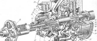
Crawler conveyor GT-SM
Manual
Table of contents
Introduction 3 Warning 5 Safety regulations and fire safety requirements 7 Technical characteristics of the conveyor 10 Purpose of the conveyor 10 Basic data 10 General characteristics 11 Filling tanks of the conveyor 18 Basic adjustment data 18 Controls and instruments 20 Controls 20 Instrument panel 23 Running in a new conveyor 25 Power plant 27 Engine 27 Engine mounting 28 Cylinder heads, crank mechanism 29 Distribution mechanism 34 Lubrication system 35 Crankcase ventilation 42 Power system 42 Carburetor 47 Carburetor care and adjustment 48 Speed limiter 48 Accelerator 50 Exhaust system 51 Cooling system 52 Starting and stopping engine 59 Starting a warm (warm) engine 59 Starting a cold engine at moderate temperatures 60 Starting a cold engine at low temperatures 61 Starting engine heater 62 Starting procedure using a starting heater 65 Caring for the starting heater 70 Rules for using the starting heater 71 Starting the engine using the starting handle 73 Stopping the engine 73 List of power unit faults 74 Transmission 81 Clutch 82 Clutch drive 84 List of clutch and drive faults 86 Gearbox 87 List of gearbox faults 92 Transfer case 93 Driveshaft 96 List of propeller shaft faults 98 Final drive 99 List of final drive faults 102 Onboard clutches 103 List of malfunctions of onboard clutches 106 Brakes List of malfunctions on brakes 107 Control drive for onboard clutches and brakes 107 Couplings and axle shafts 110 Final drives 111 List of malfunctions on final drives 112 Chassis 114 Drive wheels 114 Track chains 114 Track rollers 1 18 Guide wheels and tension mechanism tracks 121 Suspension 123 Shock absorbers 124 List of chassis faults 128 Electrical equipment 129 Battery 129 Generator 130 Voltage regulator 130 Starter 131 Engine ignition system 132 Lighting, light and sound alarm 136 Windshield wiper 141 Flexible speedometer drive shaft 141 Fuses 141 Battery switch 141 Trailer socket 142 Socket to start the engine from an external source of electricity 142 Shielded equipment 142 Care of devices 145 General rules for finding electrical faults. networks 145 List of electrical equipment malfunctions 146 Conveyor housing 149 Conveyor equipment 153 Hydrodynamic casings 153 Drainage means 154 AKM mounting 157 Sanitary equipment 157 Towing devices 160 Device for washing windshields 161 Cab and platform heating 161 Installation of license plates 164 Tools and accessories 165 Jack 166 Lever- plunger syringe 167 Pump for manual transfer of gasoline 169 Driver's life jacket 170 Engine compartment covers 170 Checking and adjusting conveyor units and systems 172 List of measuring instruments 172 Technological maps 173 No. 1. Checking and adjusting the gap between the rocker arm and the valve stem 173 No. 2. Checking and adjusting the carburetor K-126B 175 No. 3. Adjusting the carburetor to the minimum engine speed at idle 179 No. 4. Adjusting the free play of the clutch pedal 181 No. 5. Adjusting the free play of the clutch release 182 No.6. Adjusting the control drive for side clutches and brakes 183 No. 7. Adjusting the bearings of the final drive driven shaft 186 No. 8. Adjusting the locking mechanism of the gearbox 187 No.9. Adjusting the tension of track chains 187 No. 10. Adjusting the installation of balancers 188 No. 11. Adjusting the installation of shock absorbers 190 No. 12. Replacing the working fluid in the shock absorber 191 No. 13. Checking and adjusting the gap between the breaker contacts 192 No. 14. Setting the ignition timing 193 No. 15. Adjustment gap between spark plug electrodes 197 No. 16. Headlight adjustment. 198 No. 17.Adjusting the needle of the solenoid valve of the starting heater boiler 199 No.18.Adjusting the tension of the gearbox drive belts 200 No.19.Adjusting the tension of the front fan drive belts 201 No.20.Adjusting the tension of the generator and water pump drive belts 201 Rules for driving a conveyor 203 Pulling off 203 Driving and turning 203 Stopping the conveyor 206 Overcoming obstacles 206 Navigating wetlands and swamps 207 Overcoming water obstacles 208 Driving on sandy terrain 210 Driving on mountain roads 211 Driving in wooded areas 212 Driving the conveyor with a trailer 212 Towing the conveyor 213 Pulling out the conveyor 21 4 Winter operation of the conveyor 216 Features of winter operation 216 Driving in deep snow 217 Driving on slippery and icy roads 218 Driving on ice 219 Maintenance of the conveyor 220 Inspection before leaving 220 Inspection at small rest stops 221 Daily maintenance 222 Preservation of the conveyor 228 Lubrication of conveyor mechanisms 229 Lubrication chart 2 32
You can download the GAZ-71 operating instructions here
No. 4. Adjusting the control drive for onboard clutches and brakes GAZ-34039
Home / Literature / Operating manual GAZ-34039 / 20. CHECKING AND ADJUSTING UNITS AND SYSTEMS OF THE GAZ-34039 SNOW AND SWAMPSE VEHICLE / No. 4. Adjusting the control drive for onboard clutches and brakes GAZ-34039
Tools and accessories: pliers, measuring ruler, wrenches 10, 11, 12, 13, 17, 19 mm, a set of special probes for the rotating mechanism brakes.
| № | Contents and methodology of work, technical requirements |
| During the operation of the snow and swamp-going vehicle, the following types of adjustments of the control drive are carried out: – full adjustment; – operational adjustment. | |
| Full adjustment (at maintenance No. 2) | |
| 1 | Check the reliability of the connection of the rods and levers and their cotter pins. If the connecting pins and eyelets of the rod forks are heavily worn, replace the worn parts. Check the length of the brake rods. The length of the left brake rod at the centers of the eyes should be 394 mm, the length of the right brake rod should be 298 mm. |
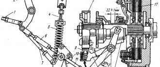
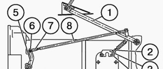
| 2 | Check the free play of the control levers to ensure that the clutches are fully engaged. The free play, measured by the control lever buttons, should be 40-50 mm. In case of violation of the adjustment: – put the control levers of the snow and swamp-going vehicle in the original (most forward) position; – remove pin 17 (see Fig. 4.9), connecting tap 16 to rod 23 (or rod 24) for controlling the clutch; – install the clutch release so that before the clutch starts to disengage, its free play of 4-5 mm, measured at the hole for pin 17, is ensured; – loosen the lock nut of the clutch linkage fork and, unscrewing (or screwing in) the linkage fork 18, align the holes for pin 17 in the linkage and the fork; – connect the clutch control rod and the release pin 17, check the free play of the control lever, pin 17 and tighten the lock nut of the rod fork; – adjust the free play of the other control lever. |
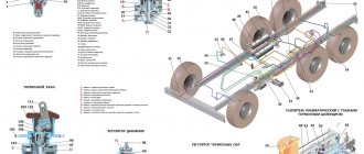
| 3 | Move control levers 1 and 2 alternately to the position of fully tightening the brake bands and, using nuts 21 of the coupling bolts, set the total stroke of the control levers to 370-400 mm. |
| 4 | Release the control levers to the extreme forward position and, using adjusting bolts 14 and 20, having previously unscrewed the lock nuts 15 and 19, set the gaps between the brake pads and the drum so that it is at least 0.7 mm. |
| 5 | Check the correctness of the adjustments by alternately installing the control levers in a fixed position on the sector teeth (lever travel 130 - 160 mm). In this position of the levers, the side clutch fans should rotate freely with a slight hand effort, and the gaps between the rear pads of the lower belts and the drums should be at least 0.2 mm. After checking that the adjustment is correct, tighten the locknuts 15 and 19 of the adjusting bolts. |
| 6 | Carry out a final check of the correct adjustment of the brakes over a distance of 20–30 km with turns and full braking. Full brake adjustment when replacing brake bands or brake pads, as well as when installing a new steering mechanism Perform a full brake adjustment as during maintenance, but taking into account the following features: |
| Complete brake adjustment when replacing brake bands or brake pads, or when installing a new steering mechanism | |
| Perform a full brake adjustment as during maintenance, but taking into account the following features: | |
| 1 | Before replacing brake bands, check the fit of the new band pads to the brake drum (the gap should be no more than 0.7 mm). |
| 2 | After installing new brake bands, during the first 300 km, when the brake pads are intensively running in, if they burn, as well as when the full stroke of the control levers increases to 450 mm, adjust them. Operational adjustment Operational adjustment is made if the total stroke of the control levers exceeds 450 mm. The adjustment is reduced to tightening the nuts 21 (see Fig. 4.9) of the coupling bolts 22 to set the total stroke of the control levers to 370-400 mm. After the adjustment, check the operation of the brakes while the snow and swamp vehicle is moving. |
| Operational adjustment | |
| Operational adjustment is made if the total stroke of the control levers exceeds 450 mm. The adjustment is reduced to tightening the nuts 21 (see Fig. 4.9) of the coupling bolts 22 to set the total stroke of the control levers to 370-400 mm. After the adjustment, check the operation of the brakes while the snow and swamp vehicle is moving. |