Motor graders are used to perform excavation work during the construction and reconstruction of roads and railways, airfields, as well as hydraulic engineering facilities.
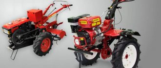
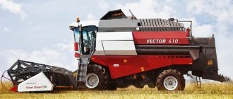
We offer a full range of motor graders - light machines for road repair and maintenance work in summer and winter, as well as motor graders for work in quarries or on large construction sites
The history of the creation of the grader by Robert Fulton dates back to 1795. At that time, the car looked like a frame with metal wheels, between the axles of which a blade was installed. This structure was moved with the help of horses. A mechanical drive was used to adjust the angle of the shovel. The operator required significant physical strength and dexterity to avoid falling while operating the blade while moving.
According to the control system for a complex of working bodies.
Mechanical or hydraulic. Working conditions and use of motor graders. Light motor graders are used to maintain and repair existing roads and create dirt roads. Medium and heavy motor graders are the main equipment used in the construction of all types of roads. As a rule, the front wheels of motor graders are steerable, sometimes the front and rear wheels are steerable. This function allows the motor grader to turn in narrow places on a small radius and carry out working movements in which the rear wheels do not move along an already profiled part of the road.
The most common are three-axle motor graders, which have two rear axles - driven and one axle, front, steered. Compared to other configurations of these units, they have better properties: more powerful traction force, the ability to maintain linear movement during operation when exposed to lateral forces and, as a result, better leveling ability. To maintain lateral stability, motor graders tilt the driven wheels using special mechanisms.
This arrangement of drive and steered axles is used today in most units of the world fleet of these machines. The main working part of the motor grader is the blade, which has a constant radius of curvature of the working surface and, in the lower part, is equipped with a working knife made of wear-resistant steel.
The angles of installation of the blade are adjusted in relation to the longitudinal axis of the unit, which is ensured by a fully rotating device for installing the blade in a horizontal plane. To move the motor grader along an arc of a certain radius, in accordance with the road route, a mechanism is used to turn the front and rear wheels in opposite directions, and when turning them in one direction, the motor grader will move translationally, at an angle to the longitudinal axis.
To increase productivity and improve cross-country ability, units with three driving axles are used, while the wheels of the front axle are also steerable. This design feature makes it possible to create a high traction force of the motor grader in poor and heavy soil conditions.
Today, motor grader designs are developing in the direction of increasing the power of the main engine, with the same mass of the unit, using hydromechanical transmissions in the chassis, using diesel engines operating at significant rolls, at low and high temperatures and at high dust levels, increasing the transport speed of the unit, and automating control working bodies, for profiling the road in automatic mode, improving the working conditions of the driver-operator.
The most common layout today is the kinematic diagram of a three-axle unit, in which two rear axles are driven, and the front axle is only steered.
Features of the grader
The blade blade is operated via a control panel in the grader cabin. The shovel can rotate 180–360 degrees in any direction.
Depending on the grader’s configuration, purchased machines may additionally be equipped with automatic control devices from different manufacturers. This equipment allows you to move and level soil with an accuracy of 5 mm.
For the same purpose, technologies based on ultrasonic radiation, sensors for measuring slopes, and technologies based on light radiation are used.
Important. Using motor graders together with bulldozers and other road construction equipment significantly reduces work time and increases the overall efficiency of the machines involved.
Motor graders and grader-elevators
Motor graders
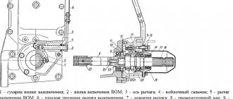
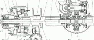
— self-propelled road vehicles, the working equipment of which is a movable blade (Fig. 1). In addition to the main equipment - the blade - replaceable working parts are installed on the motor grader: a small bulldozer blade, a pick for preliminary loosening of dense and heavy soils, a snow blower, a road milling machine, etc. The motor grader has a hydraulic control system for the main blade, which ensures its horizontal rotation by 360° and tilt together with the traction frame up to 90°.
Fig.1. Motor grader:
1
,
2
,
3
- hydraulic motors for controlling the picker, tilting and rotating the blade;
4
— basic tractor;
5
- distributor;
6
- pump;
7
- rotary column
This design of the machine ensures its purpose and scope of application: profiling and finishing of the road subgrade, installation of crushed stone, gravel and sand road surfaces, construction of low (up to 0.6 m) embankments from lateral reserves, planning work, snow removal, etc. Main The purpose of the motor grader is profiling the road subgrade. The greater the resistance and the more difficult the working conditions, the more powerful the motor grader must be. Depending on the engine power and weight of the machine, light (up to 100 kW; 9 t), medium (100...150 kW; 10...15 t) and heavy (over 160 kW; over 15 t) motor graders are produced. Light motor graders are used for road maintenance, medium ones - in road construction in medium-density soils, and heavy ones - for large volumes of excavation work in dense soils and construction of road surfaces. The design of most motor graders is unified; it includes the main frame, traction frame, turntable with blade, engine, transmission, running equipment and control system. The traction force, maneuverability and stability of a motor grader are characterized by the design of the chassis. Depending on the production and technological requirements and working conditions, motor graders with a different number of wheels and drive axles, as well as a control system for axles and wheel tilt, are used (and are produced by industry for this purpose). The wheel layout of a motor grader is indicated by the formula, in which is the number of axles with steered wheels, is the number of driving axles, and is the total number of axles. The most common are motor graders with a 1x2x3 wheel arrangement.
Ways to increase the productivity of motor graders consist of increasing the operating speed of the machine, reducing the time for preparatory operations, reducing the loss of working time and reducing the number of passes in one place due to the automatic control of the grader blade by the “Profile” systems.
Grader-elevator
- a continuous earth-moving and transport machine that develops soil with a disk or flat knife and delivers it to a dump or vehicles via a belt conveyor (Fig. 2). To develop the soil, the knife is lowered onto the ground; as the machine moves, it develops and dumps the soil onto a running belt conveyor. The latter lifts soil to a height of up to 4 m, moves it in the transverse direction (to a dump or to vehicles) at a distance of about 10 m. The presence of a conveyor makes it possible to build low embankments up to 1.5 m from lateral reserves, and arrange shallow embankments up to 1.5 m trenches.
Thanks to the principle of continuous layer-by-layer soil development incorporated into the design of the machine, the grader-elevator has high technical productivity - more than 600 m/h. However, its implementation requires a number of stringent operating conditions: flat terrain; the absence of large (over 150 mm) stone inclusions that can damage the disc knives, the presence of a sufficient work area of 200 m or more. These limitations significantly narrow the scope of effective use of grader-elevators. Their share of production in the total volume of earthworks does not exceed 1%.
Fig.2. Grader-elevator:
1
- frame;
2
— hydraulic motors for controlling the conveyor;
3
- conveyor;
4
— pneumatic wheel travel;
5
- cutter
Ways to increase the productivity of a grader-elevator include improving the technology of its use and thoroughly examining the soil conditions at the reserve site in order to detect stone inclusions and vegetation that can lead to the machine stopping or damaging it. The productivity of the machine increases if the embankment is poured from a double-sided reserve, since this eliminates the cost of working time on an empty move.
EARTHWORK USING GRADERS AND MOTOR GRADERS
Graders and motor graders are designed for profiling dirt roads with the construction of side ditches, for the construction of road embankments, dams, shafts from side reserves, leveling of the roadbed, slopes, construction of the roadbed and terraces on steep slopes, as well as troughs in the finished roadbed for the construction of road bases .
Medium and heavy graders and motor graders are also used for mixing soil and gravel-crushed stone materials with binder additives on the road surface; when constructing and cleaning irrigation canals and for repairing and maintaining roads.
Figure 3 shows an example of constructing a 7 m wide embankment using two graders, of which grader 1 (the more powerful) cuts the soil from the inner edge of the reserve, and grader 2 moves it and develops it. The graders move sequentially one after another, performing work in circular passes. The number of passes depends on the height of the embankment and the depth of the reserves.
Fig.3. Scheme of simultaneous operation of two graders:
1
,
2
— graders
Figure 4 shows a diagram of leveling the bottom of the reserve using a grader. This scheme is also suitable for other cases of planning work.
Fig.4. Scheme of leveling the bottom of the reserve with a grader:
1-20
— passage numbers
When leveling the bottom of the reserves, the grader makes circular passes along the roadbed along the right and left reserves. The number of passes depends on the width of the reserve. At least two passes must be made in one place. Graders-elevators are designed for layer-by-layer cutting and moving soil to a dump at a distance of up to 15 m or to a vehicle during the construction of road embankments and dams using soil from lateral reserves, development of excavations, excavation of channels and pits, as well as during stripping operations in quarries. A grader-elevator is a continuous earth-moving machine for layer-by-layer cutting, with a transport device in the form of a belt conveyor or thrower.
Graders (Fig. 5) are intended for planning and profiling work during the construction of roads, airfields and other linear and areal objects. Based on the difficulty of development by graders, soils are divided into groups I, II and III. Graders are applicable in soils above the groundwater level and are ineffective in wetlands.
Fig.5. Design and operating diagrams of the grader:
A
- side view;
b
- cutting soil;
c
,
d
- planning of the road surface of the excavation slope;
g
- blade rotation;
1
- frame;
2
- turntable;
3
— traction frame;
4
— traction frame axis;
5
— turntable axis;
6
- blade
The efficiency of the graders is ensured with working moves longer than 0.5 km. Grader elevators (Fig. 6) are used when digging soil of groups I…III in flat areas and dumping it into linearly extended earthen structures from lateral reserves. They are divided into semi-trailer (for tractors) or mounted (for motor graders).
Fig.6. Schemes of operation and aggregation of grader elevators: a
,
b
- construction of a road embankment and canal;
c
,
d
- semi-trailer and mounted grader-elevators;
1
- conveyor;
2
- plow
Graders are used when leveling the territory, slopes of earthen structures, cleaning the bottom of pits and digging ditches up to 0.7 m deep, when constructing extended embankments up to 1 m high and the lower layer of higher embankments from reserves. Motor graders are used to profile road surfaces, driveways and roads. When constructing an embankment from a developed reserve (Fig. 7), an inclined knife moves the cut soil towards the embankment. The next time the grader passes, this soil moves even further in the same direction. Therefore, it is advisable to work simultaneously with two graders, one of which cuts and the other moves the cut soil. It is most effective to use motor graders with a penetration length of 400...500 m. Dense soils should be loosened with a tractor ripper or plow before development with a grader. In addition to developing the soil and moving it over short distances, the grader can be used to level and thoroughly grade the soil. When performing various operations, the angles of inclination of the grader blade change within the following limits: grip angle 30...70°, cutting angle 35...60°, tilt -2...10°.
Fig.7. Scheme for developing a reserve using a motor grader:
— grip angle; — cutting angle; — inclination angle To ensure optimal operation of earth-moving machines, systems have been created to automatically control the speed of their movement depending on the cutting resistance and density of the soil being developed. For motor graders used primarily for leveling work, devices are used that automatically control penetration into the ground.
Classification and basic construction properties of soils
Based on their structure, soils can be divided into cemented (or rock) and uncemented.
Rocky soils consist of rocks that are difficult to mine by blasting or crushing with wedges, jackhammers, etc. The skeleton of unconsolidated soils usually consists of sandy, silty and clay particles, depending on the content of which the soils are called: sand, sandy loam (sandy loam), loam, clay (Table 1).
Optional equipment
Self-propelled graders have several pieces of auxiliary equipment. Due to such auxiliary equipment, the capabilities of the machine are expanded:
- Bulldozer blade – controlled by a hydraulic cylinder;
- The bale machine is a multi-rack loosening equipment intended for breaking up road surfaces;
- Picker - mounted on mounts from the rear of the main rotary blade;
- Extenders - also considered replaceable equipment, intended to lengthen the working body, are fixed on the main blade;
- Slopes – designed to form slopes of embankments and excavations;
- Swept blade - designed for clearing roads and large areas of snow, can be installed instead of a bulldozer blade.
Before starting work, it is necessary to carry out debugging measures to configure the working body (blade). During the period of work on the motor grader, its control is limited to the regulation of high-speed systems, maintaining the route of the technical equipment and establishing the vertical position of the blade and the angle of transverse inclination. To construct slope embankments, the blade is moved to the side relative to the overall size of the motor grader. The soil mass in front of the machine's blade moves clearly in the same way as in front of the blade of a multi-purpose bulldozer. The effectiveness of a technical means during the period of execution of planning events is calculated in the same way as a multi-purpose bulldozer.
Specifications
There are several dozen options for working equipment. When wondering how to choose special equipment, decide what a motor grader is needed for. When purchasing, you should pay attention to the engine power, the weight of the unit, the dimensions of the blade, and the speed of the machine.
There are several popular models of levelers on the market:
1. DZ-98. The weight of the machine reaches 20 tons. The ground clearance is 35 cm, the turning radius is 18 meters. The transmission consists of a manual gearbox and a 2-disc clutch. The braking system allows blocking of all axes.
2. D3-122. The main purpose of this equipment is excavation work. The car weighs 14 tons. The power of the 6-cylinder diesel engine is 150 horsepower.
3. D3-180. This model of working equipment is equipped with a hydraulic control system. The engine runs on diesel.
The chassis may have two or three axles. On the rear frame, as a rule, there are 2 pairs of wheels.
Structure of SEM graders
We will analyze the design of a motor grader using the example of SEM technology, based on 4 main components:
- Transmissions.
- Hydraulic system.
- Frames and blade.
- Cabins with control mechanism.
Transmission
The engine on SEM motor graders is a simple and reliable mechanism, it works effectively in difficult weather conditions, withstanding temperatures from -40°C to +50°C. Power varies from 190 to 220 hp. Environmental friendliness corresponds to Stage II class, noise does not exceed 111 dB.
The motor graders are equipped with an automatic hydromechanical gearbox. The torque converter increases the efficiency of the machine's engine and reduces fuel consumption. The front axle on all versions of the manufacturer contributes to the optimal inclination of the wheelset. Reliable stopping is ensured by brake drums.
Hydraulic motors are installed in the wheel hubs (front). This allows the vehicle to confidently move in off-road conditions and increases traction with the ground. Hydraulic motors also provide creeping speed, which makes it possible to start and stop smoothly without leaving ridges on the blades.
"If a motor grader has hydraulic motors installed in the front wheel hubs, this will allow the equipment to confidently move in off-road conditions and increase traction with the ground."
Hydraulics
Thanks to the development of a hydraulic system, SEM specialists ensured precise and fast control of the equipment. The installed axial piston pump makes it possible to:
- Save fuel.
- Reduce slippage.
- Reduce wheel wear.
- Increase traction force and overcome load.
- Reduce work cycle time.
The PPPC (Proportional Priority Compensation) unit, part of the SEM hydraulic system, ensures uniform speed of movement of the blades, as well as the rear ripper, and the movement of other working tools.
Blade frames
The equipment has the longest wheelbase. Thanks to this, the blade can be installed at a large angle, which reduces power consumption. The traction frame has a box-shaped section, it is powerful, and is suitable for fixing various attachments. The drive teeth of the solid-forged turntable are heat-treated with high-frequency heat, they are wear-resistant and can withstand extreme loads. The turntable is fixed to the frame with six support shoes. Design features reduce friction with the rotating frame.
The durable rear trolley serves as an excellent support for the working tool and protects the power transmission from excessive loads that appear when cutting, picking, clearing, and other work.
Control
The motor grader is controlled from a comfortable cabin with a large overview. It is located on the front half frame. Control is carried out with minimal effort, the lever travel is the shortest in its class - 20 mm. This makes it possible to control several levers at once with one hand. The noise level in the cabin does not exceed 77 dB. The height of the cabin (1.9 m) allows you to work while standing.
Range of application of graders
This type of working equipment is used in almost all industrial sectors. It is useful for leveling sites after the work of special earthmoving equipment. Motor graders are often used in agriculture. The machine can be put into operation immediately after purchase.
In winter, motor graders are needed for road maintenance. Using this technique, you can remove snow and ice from the road. The purpose of the vehicle determines what the car looks like. For example, some types of special equipment are equipped with a pick or slope.
Design
Automotive types of graders are produced according to a scheme that is the same for all representatives. Such machines must be self-propelled and have three axles. The control system must be equipped with hydraulics, and the blade must be fully rotatable.
Self-propelled graders have an original type design, which is also long-base.
For example:
- The device has an excellent direction for high-quality planning of work with soil, as well as its profiling. This is achieved by ensuring that the working element is placed according to the correct priority;
- The three-axle base of the motor grader provides the driver with increased comfort and ease of control.
The design of this type of device consists of the following details:
- The basis is a special frame, long and with a hump in the middle. It is on this basis that all the necessary points of this device are established;
- At the rear there is a trolley that has balancers. Such balancers are supplemented with pneumatic wheels;
- The front also has its own balancers, which help steer the front wheels;
- Such a device is nowhere without an engine;
- This device also includes a transmission. Due to it, force is transmitted from the engine to the drive wheels;
- Blade device. The device is located under the frame in the place where it has a hump. It is also called “spine beam”. The entire device is attached using a hinge;
- There is a cabin in which the control panel for the entire machine and organ is located;
- There is a hinged hood that protects the engine from debris and other particles.
Self-propelled graders of domestic production are all based on engines that have a power of about 45 kilowatts. If we talk about a similar device, but of the middle class, then the power increases and amounts to 82 kilowatts. With maximum engine capacity, power can reach 120 kilowatts. The engine is located on the frame at the rear. The driver's cabin is located in front of the engine. This frame also has transmission elements.
The front part of the frame of this device has a bridge, which includes wheels. This type of vehicle can be driven pneumatically. All this is installed with additions as hinges. There is also a longitudinal type axis, which is auxiliary. The rear axle is produced using a four-wheel design.
This design of the wheels in this device allows them to be loaded to the maximum, and they will receive the load extremely evenly. Due to this, it is possible to significantly reduce the vibration impact on the frame. The service life of the machine is significantly increased, and productivity also increases.
The basic type frame has a traction frame. The connection of the two frames is carried out by a hinge. The additional frame has the ability to both rise and fall due to auxiliary hydraulic cylinders, which are installed on the sides.
The traction type frame has a rotating circle, where ordinary brackets serve as auxiliary devices. The rotation of such a circle occurs due to a hydraulic motor. A special shaft is installed on the brackets. The design allows for cutting the soil at absolutely any possible degree. You can also rotate the organ and move it along the entire length of the axis.
The front wheels have an additional tilt, making it possible to achieve stable movement of the vehicle as a whole on various types of terrain. This advantage helps if there are large angle slopes. This helps cars to clear roads of snow during winter.
Types of motor graders
The classification of motor graders is based on the type of wheels, the weight of the motor grader, its power, the type of transmission and final drives, and the type of frame. Motor graders are produced with metal and pneumatic rear and front wheels. In the first case, the price of the equipment is lower, it is easy to repair, and does not require large investments in maintenance. The disadvantages include low speed. The pneumatic wheel design is more expensive and more difficult to maintain, but equipment with such equipment moves faster - up to 30 km/h.
By weight and power, graders are divided into:
- LUNGS. Weight up to 12 tons, power -75-90 hp. Designed for planning and marking.
- MEDIUM. Weight is from 13 to 15 tons, power is 120-150 hp. The main functions are reconstruction, mixing of materials on site, road profiling. (SEM 919, SEM 921, SEM 922 AWD)
- HEAVY. Weight is 19-20 tons, power reaches 300 hp. Used in road construction.
There are motor graders with mechanical and hydromechanical transmission. In the first case, the speed is changed manually in steps. With hydromechanics this happens automatically and smoothly. All SEM equipment, including motor graders, are equipped with a hydraulic transmission. This provides the operator with more confident control of the machine, and as a result, faster completion of construction tasks.
» Motor graders with mechanical and hydromechanical transmission are sold on the market. In the first case, the speed is changed manually in steps. With hydromechanics this happens automatically and smoothly. All SEM motor graders are equipped with a hydraulic transmission."
A little about SEM motor graders. The equipment has an economical engine, and the cooling system allows operation even at -40°C. The hydromechanical transmission makes it possible to change speed when the vehicle is under load. The hydraulic system increases control accuracy and ensures smooth movement. The cabin is comfortable with a wide viewing angle. The battery starts easily even with a serious minus on the street, which is important for the Russian climate. The grader is used for making slopes, removing snow, and leveling the road surface.
The next classification point is final drives. Light and medium motor graders have a side gearbox, while heavy ones have separate drive axles.
The frames in the design are rigid and articulated. The first ones are strong, but immovable, the second ones are more maneuverable.
Also, the classification of motor graders involves division by the number of axles. There are two-axle and three-axle machines.