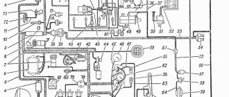
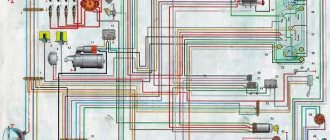
The contactless ignition system (Fig. 1) includes the following devices:
Rice. 1. Diagram of a non-contact ignition system
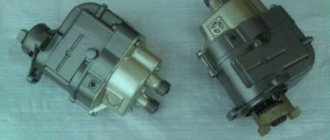
The device of the sensor-distributor is shown in Fig. 2.
The distribution sensor has a housing, a cover, a roller, a sinusoidal voltage sensor, centrifugal and vacuum regulators, as well as an octane corrector.
The centrifugal regulator automatically changes the ignition timing depending on the rotation speed.
The voltage sensor consists of a rotor and a stator.
The rotor is a ring permanent magnet with four-pole cages tightly pressed to it from above and below, rigidly fixed to the sleeve.
A runner is installed on the bushing in the upper part of the rotor.
The sensor stator is a winding enclosed in four-pole plates.
The stator has an insulated stranded lead connected to the sensor lead.
The second terminal of the winding is electrically connected to the housing in the assembled sensor-distributor.
There is a mark on the rotor and an arrow on the stator, which serve to set the initial moment of sparking.
Ignition coil
(Fig. 3)
Winding resistance at temperature (25±10) °C, Ohm:
secondary. 13,000–13,400
Developed secondary voltage maximum, V. 30,000
The coil has a high voltage terminal and two low voltage terminals:
– terminal K – for connection with terminal K of additional resistance;
– unmarked output – with output K3 of the switch.
Additional resistance
(Fig. 3)
The value of active resistance between terminals “+” and “C” is (0.71±0.05) Ohm, between terminals “C” and “K” – (0.52±0.05) Ohm.
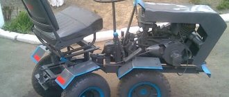
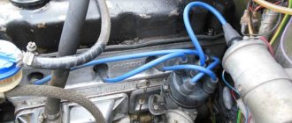
Many UAZ owners know about the vagaries of classic ignition, which sometimes presents unpleasant moments. And often craftsmen find ways to modernize a problematic unit or an entire system. And one such method of improving the launch system with your own hands will be discussed in this publication. In the photo, UAZ 31514 is a reliable all-terrain vehicle for many purposes.
General concept
The contact ignition circuit itself is not bad, because humanity has been using it since the advent of the first car. But, of course, it is far from the capabilities of contactless ignition. Therefore, many UAZ owners, in an effort to improve the performance of the power unit, reconfigure it.
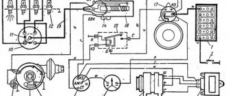
General ignition circuit for older UAZ models
And not only UAZs, but also other domestic cars, for example, the wiring of the Moskvich 2141 and a number of other brands and models are subject to alterations.
Effect of modernization
What is important is that the engine compartment and interior electrical wiring of the UAZ 31514 remains virtually unchanged, and the alteration itself is characterized by the installation of new elements under the hood.
As a result:
- The engine begins to operate stably in all modes;
- Improves cold starting;
- Fuel consumption is normalized;
- The engine power will reach the passport data.
Differences between ignition systems
The main difference between the two systems is the moment of sparking:
- In classic ignition, a slider under the distributor cover is responsible for this when it comes into contact with the output contact on the spark plug wire. In this case, the supply of a high-voltage pulse occurs with an increase. It seems to be lubricated, reducing the spark power at the spark plug electrodes.
- In contactless ignition, the switch generates a charge and releases it almost instantly upon receiving a signal from the Hall sensor. As a result, the candle produces a more powerful spark. Among domestic off-road vehicles, the Niva has a similar contactless ignition system - see the VAZ 21213 wiring diagram.
The electronic switch is often mounted in UAZ vehicles on the partition on the left side.
Please note! More powerful sparking promotes self-cleaning of the spark plug, because The fuel burns intensively, leaving no deposits.
Historical excursion
The history of the UAZ 31514 began long before the nineties - in peacetime they wanted to get more functionality from the legendary UAZ 469, which led to its deep modernization.
As a result, its “civilian” version of the UAZ 469B appeared, which was distinguished from its predecessor:
- The drive axles have lost their final drives, which provide tremendous off-road maneuverability;
- The preheater was removed from the car;
- The open body was equipped with a canvas awning;
- The power unit was the UMZ-414 engine with a power of 80 hp.
For reference: a metal awning, and later a fiberglass one, was offered as an additional option. The manufacturer also managed to reduce costs - the price did not change significantly.
Restyling
The manufacturer did not dwell on the result obtained, and in 1993 released a new model - UAZ 31514, which completely replaced the UAZ 469 on the factory assembly line.
- Power unit UMZ-4178 carburetor type, volume 2.5 liters;
- The car was also equipped with a ZM3-4021.10 engine, which, with equal parameters, produced 3 hp more. more;
- Later modifications were equipped with a ZMZ-5143.1 diesel engine equipped with a turbocharger;
- Hardtops became the norm, and were installed on an assembly line;
- The front suspension became spring (the promotional video of those years was based precisely on this improvement);
- The car received a front wheel disengagement clutch;
- An improved interior has become the norm (adjustable seats, soft upholstery, radio), and therefore the interior electrical wiring of the UAZ 31514 has also changed.
For reference: the ZM3-4021.10 engine was interesting due to its compliance with EURO-2 environmental standards. In this configuration, the car could be sold abroad.
Features of the electrical circuit
Among the most noticeable features of the UAZ 31514, which distinguishes it from its predecessors, is a split windshield with windshield wiper gears moved under the roof. Thanks to this solution, the UAZ 31514 wiring received an additional wiring harness for connecting them.
Also on the car there was a contactless ignition system previously tested on its predecessor, consisting of (in order):
- Low voltage ignition coil;
- Transistor electronic switch;
- Sensor-distributor (distributor);
- Electric spark plugs;
- Fuse box;
- Emergency breaker;
- Additional electrical resistance;
For reference: The wiring in the diagram is indicated by capital letters of color - K (red), G (blue), Zh (yellow), Z (green).
Rework
Actually, the work itself comes down to remaking the distributor, which will no longer have a high-voltage part - an electronic switch will generate high-voltage pulses for it . The photos below show the location of two sensors at once.
The sensors are attached to the base and the contact plate has curved edges
Pay attention to the shape of the contact plate:
- It has curved ends - the sensors are located vertically;
- Flat – the sensors are mounted horizontally.
Flat plate option
Flat plate option
Both options are working, it all depends on the design of the distributor. In the future, you only have to adjust the ignition. The instructions are simple - you must remember that sparking begins when the edge of the plate is in the center of the Hall sensor.
The order is as follows:
- Rotate the crankshaft until the piston in the first cylinder reaches TDC;
- Rotate the distributor body until the contact plate is in the sensor slot;
- Carefully tighten all mounting screws to eliminate any play.
- Start the engine.
Review of SZ on famous UAZs
What is the connection diagram for electronic or contactless ignition on a UAZ 417, how to convert contact ignition to contactless? Why does the coil heat up and how to adjust and adjust the advance angle? First, let’s look at the main points regarding the action and types of SZ.
Operating principle of SZ
Contact system diagram
The ignition system, or rather its correct setting, plays a big role in the operation and starting of a car engine. With correct adjustment, the combustible mixture will burn correctly in the power unit as a result of the supply of charge through the spark plugs. A spark plug is placed on each cylinder of the UAZ engine, each of which is turned on in a certain order, in turn, delivering a discharge to the cylinder after a certain time. It must be taken into account that any SZ makes it possible not only to deliver the required discharge, but also determines its strength.
terms of Use
Experienced car enthusiasts assessed the car modification differently. In comparison with its predecessor - UAZ 469, the new “three hundred and fifteenth”:
- Became more comfortable, which was facilitated by alterations to the interior and chassis;
- It lost its off-road qualities because it received gearboxes with changed gear ratios.
In practice this was expressed as follows:
- When used in off-road conditions, the old 469 easily overcame mud thanks to its “military bridges”;
- The new UAZ could be “buried” in swampy areas due to the installation of “civilian” bridges;
- The maximum speed of “469” did not exceed 90-100 km/h on the highway;
- The new UAZ 31514 accelerates to 120-130 km/h.
Many UAZ owners know about the vagaries of classic ignition, which sometimes presents unpleasant moments. And often craftsmen find ways to modernize a problematic unit or an entire system. And one such method of improving the launch system with your own hands will be discussed in this publication.
In the photo, UAZ 31514 is a reliable all-terrain vehicle for many purposes.
Expert recommendations on how to configure correctly
So, how to set the advance angle yourself in order to achieve proper operation of the UAZ engine:
- First of all, you must lock your car in one place by pulling the parking brake lever. Rotate the crankshaft so that the piston of cylinder 1 reaches TDC (top point). In this case, you need to ensure that the hole on the crankshaft pulley coincides with the mark marked on the timing gear cover.
- After this, remove the cover from the distribution mechanism. After dismantling, you will be able to see the slider, which is located inside the cover itself, opposite the contact. If there is no slider, you should turn the crankshaft 180 degrees again, and then set the octane corrector to 0. Using a wrench, you will need to screw the pointer to the distribution mechanism housing so that it aligns with the middle mark. When these steps are completed, the fastening bolt with which the plates are attached to the distributor body must be loosened slightly.
- Then, holding the slider in one place with a finger to prevent it from rotating, you need to carefully rotate the housing itself, this will allow you to remove possible backlash in the drive. The housing must be rotated until you achieve alignment of the sharp end of the stator mechanism petal with the red mark located on the rotor device. After this, the plate itself must be secured to the body using the appropriate bolt.
- Once you have completed these steps, you need to replace the controller cover and check the high voltage cables. You need to make sure that these wires are installed in the correct sequence, taking into account the firing order of the cylinders. When you manage to correctly adjust the lead angle, you need to make sure that the entire procedure was performed correctly.
- To diagnose the correctness of the actions performed, you need to start the engine of your UAZ and wait about 5-10 minutes until the power unit warms up. The operating temperature of the engine is about 90 degrees; you can wait until the internal combustion engine warms up to 80 degrees. Then you need to drive onto a flat road and accelerate the car to 40 km/h, after which you should sharply press the gas. At this moment, the car will accelerate and if, when the speed increases to 60 km/h, a short-term detonation (metallic knock) is heard from under the hood, then this indicates that all actions were performed correctly. If the detonation is too long, the system will need to be adjusted. To do this, the housing of the distribution mechanism will need to be turned one notch or half, and it must be turned counterclockwise. If the diagnostics showed that there is no knocking of the “fingers” at all, then the advance angle should be increased. To do this, the mechanism should be turned in the opposite direction.
Description and types
The ignition coils of the UAZ Patriot SUV series 3012.3705 are made in the form of a high-voltage pulse transformer without oil filling (dry type). They are equipped with closed magnetic circuits, the primary and secondary windings of which are isolated from each other. To connect low-voltage circuits from a battery or generator, a connector is provided in the upper part of the housing. The connection to the spark plugs occurs without the use of high voltage wires, with direct contact. The coils are fastened using screws through the mounting holes.
A guide to replacing a distributor with an oil pump drive
Before installing a new distributor with a drive, you need to weigh your strengths, since it is not recommended to make mistakes when performing work.
So, how to replace and install the distributor:
- Turn off the ignition and remove the distributor cover; the tips and high-voltage cables are connected to it.
- Then you need to disconnect the wire connected to the switch from the distribution mechanism. You also need to disconnect the pipe connected to the vacuum regulator.
- Taking a 13mm wrench, unscrew the two nuts securing the device and remove the mechanism along with the oil pump drive from the power unit.
- After completing these steps, you will be able to see the gasket located under the drive. If as a result of these actions the position of the crankshaft has not changed, then simply install a new mechanism, making sure that the slider is located opposite the mark. All actions are performed in reverse order. When the installation is completed, the advance angle is adjusted.
- If, as a result, the location of the shaft has changed, then before installation it is necessary to move the piston of cylinder 1 to top dead center. You need to ensure that the marks on the pulley align with the pointer on the motor itself.