Removal and disassembly of the final drive T-170
Drain the oil from the final drive. Disconnect the track, remove the cab with the fuel tank and wings (see “Repair of the T-170 gearbox”), the final clutch, the drive wheel and the labyrinth seals.
Rice. 247. Final drive of tractor T-170.01
Remove plug 6 (Fig. 247) from the keyway of axle shaft 16. Press out key 7 and remove rubber ring 5 and steel ring 4 from the axle shaft. Unscrew the nuts and bolts securing the final drive housing.
Rice. 248. Final drive sling diagram
Sling the final drive casing behind the hole in the rib (Fig. 248). Screw two release bolts into the M14 holes, slide the casing off the pins and remove it.
Rice. 249. Hub strapping diagram
Snap the hub (Fig. 249) with the gear and remove it from the axle shaft together with roller bearing 8 (see Fig. 247), sleeve 2, ball bearing and outer ring of roller bearing 17.
Use a socket wrench to remove six bolts 14 through hole C in the drive flange. Screw two M12ХК75 release bolts into the bearing housing.
Rice. 250. Scheme for slinging the leading flange
Secure (Fig. 250) the drive flange with the gear and press the bearing housing out of the seat using the release bolts. Remove the drive flange with gear 15 (Fig. 247) from the side clutch compartment.
Rice. 251. Double gear
Sling the double gear. Gear weight 40 kg. Loosen and unscrew the nut (Fig. 251) and remove the clamp 3. Remove the double gear with the inner rings of roller bearings 4 and 9. Unscrew the six bolts 12 and remove the clamp 6. Using a copper mandrel, knock out the bearing housing 10 along with the rod, ball bearing and outer ring of the roller bearing . Press out the ball bearing together with the outer ring of the roller bearing and remove rod 5.
Disassembling the T-170 hub
Rice. 252. Hub
Bend the ends of the locking plates 3 (Fig. 252) and unscrew the nuts from the bolts 5 securing gear 4 and ring 12 to hub 13. Knock out the bolts, remove them and strips 6. Remove the gear and ring. Press out the outer ring of roller bearing 1 with a puller and, if necessary, remove the retaining ring 14.
Turn the hub over with cover 10 facing up. Bend the ends of the locking plates 7 from the edges of the heads of the bolts securing the cover 10 to the end of the hub. Unscrew the bolts and remove the cover. Use a puller to press out ball bearing 9 together with the outer ring of roller bearing 8. If necessary, remove retaining ring 11.
Dismantling the T-170 drive flange
Rice. 253. Leading flange
Unlock and unscrew bolt 14 (Fig. 253) and remove the locking plate. Unscrew the nut 42 from the end of the drive gear 5 and remove the metal ring 13 and the rubber gasket 11. Press the flange 10 from the splines of the drive gear. Remove the cover 9 from the housing and press the cuff 15 and the ball bearing 17 out of it. Press the outer ring 6 of the roller bearing out of the housing 18 with rollers and separator.
Dismantling the final drive casing T-170
Unscrew bolts 11 (see Fig. 247) and remove cover 10 with gaskets 9.
Rice. 254. Final drive housing
Unfasten and unscrew the bolts 6 (Fig. 254) and remove the clamps 7 and locking plates 5. Press the outer ring of the roller bearing 8 with the rollers and separator out of the casing 4 using a puller. Unscrew stopper 9 from the casing. Press out the outer ring of the roller bearing 3 c. rollers and separator.
The housing, pinion hub and double pinion can be removed without removing the cab, fuel tank or final clutch.
Specifications
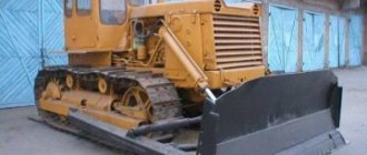
Technical characteristics of the T-170 crawler bulldozer:
| Characteristics | Indicators |
| Engine | D180.111-1/D-160.11) |
| Power, hp (kW) | 180(132)/140(103) |
| Fuel consumption (specific), g/kW*h (g/l.s.h.) | 218 (160) |
| Transmission | mechanical/hydromechanical |
| Ground pressure, MPa | 0,03/0,042 |
| Blade width, mm | 4260 |
| Max. rise, mm | 1220 |
| Max. depth, mm | 470 |
| Size, LxWxH, mm | 6255x4260x3145 |
| Mass (weight), kg | 19560 |
The video shows the T-170 bulldozer in action:
Technical requirements of the final drive T-170
- Press in the outer and inner bearing races and the double gear bearing housing until they stop.
- The outer and inner rings of bearings of the same name must have the same markings. Dismantling. bearing rings are not allowed.
- Before assembly, the rubbing surfaces of the bearings and cuffs should be lubricated with TEP-15 transmission oil.
- After assembling the final drive, check the runout of the drive flange. Allowed runout of surface K (see Fig. 247) is no more than 0.5 mm, surface I is no more than 1 mm on a diameter of 380 mm,
- The misalignment of the main gear bevel gear shaft and the final drive drive flange is no more than 0.55 mm. The non-parallelism of their axes is no more than 1 mm on a diameter of 380 mm.
- Double gear:
- length of the common normal of the small crown 55.002-0.25 mm
- length of the common normal of the large ring of the double gear 70.078-0.35 mm
- the interference between the ball bearing 70-32417М and the gear journal is 0.013…0.055, the permissible interference is 0.0 mm, the maximum clearance is 0.1 mm.
- the interference between the roller bearing 70-32612К and the gear journal is 0.011…0.045 mm, the permissible interference is 0.0 mm, the maximum clearance is 0.1 mm.
- Casing:
- pairing between. roller bearing 70-32417M and housing seat should be from interference 0.016 mm to clearance 0.060 mm, permissible clearance 0.080 mm, maximum clearance 0.2 mm;
- the interface between the roller bearing 70-32612K and the casing seat should be from an interference of 0.014 mm to a clearance of 0.044 mm.
- Ball bearings are installed with clearance along the inner diameter.
- Driven gear:
- the length of the common normal of the external teeth is 186.46 mm, the permissible length of the common normal is 185.0 mm;
- the length of the common normal of the internal teeth is 154.58+0.40 mm; the permissible length of the common normal is 155.7 mm.
- Crown:
- the length of the common normal is 154.58-0.15 mm; the permissible length of the common normal is 153.4 mm.
- Drive gear:
- the length of the common normal is 44.467-0.16 mm, the permissible length of the common normal is 43.10 mm;
- the interference between the roller bearing 70-32612К and the gear journal is 0.011…0.045, the permissible interference is 0.0 mm, the maximum clearance is 0.1 mm;
- the interference between the roller bearing 70-32315 and the gear journal is 0.011…0.045 mm, the permissible interference is 0.0 mm, the maximum clearance is 0.1 mm.
- There is an annular groove on the surface under the cuff at the leading flange; risks are not allowed. If there are gouges and scratches, treat the surface until they are eliminated, but to a size of at least 99.25 mm.
Assembly of final drive T-170
Assembling the T-170 drive flange
Heat the inner rings of roller bearings 4 (see Fig. 253) and 6 in an oil bath to a temperature of 363-383 K (90...110°C) and press onto the journals of gear 5 until they stop at the support ends. Install the clamp 3 and secure it with two bolts 1 with a locking plate 2. Bend the ends of the locking plate on the edge of the bolt heads. Press the outer ring of roller bearing 6 into the bearing housing 18 until it touches the housing shoulder. Press ball bearing 17 into cover 9 until it stops against the collar. Turn over the cover with the bearing and press the cuff 15 into it until it stops against the ball bearing with the sealing edge towards the bearing. Install the bearing housing with the outer ring onto drive gear 5. Install rings 7 and 8 into the housing. Place rubber ring 16 on the cover and install it into the housing until it stops against ring 8. Press flange 10 onto the splines of the drive gear. Place flange 10 onto the threaded end of the drive gear rubber gasket 11, steel washer 13 and screw on nut 12. The tightening torque of the nut is 245…294 Nli (25…30 kgf-m). Place the locking plate on the nut and secure it with bolt 14. Bend the edge of the locking plate onto the edge of the bolt head.
T-170 hub assembly
Install the hub with the flange facing up. Install crown 12 on it (see Fig. 252). Place gear 4 on the ring gear. Place strips 6 on bolts 5 and press the bolts into the holes of the ring gear and hub. Install ring I into the groove of the hub and press ball bearing 9 into the ring until it stops. Press the outer ring 8 of the roller bearing into the hub until it touches the ball bearing. Install the cover 10 and secure it with eight bolts with locking plates 7. The tightening torque of the bolts is 40...60 N•m (4...6 kgf•m). Bend the ends of the locking plates at the edges of the bolt heads. Turn the hub over with the flange facing down. Place locking plates 3 with their bent ends up on bolts 5, pressed into the holes of the crown and hub, and screw nuts 2 onto the bolts. The tightening torque of the nuts is 200...300 N • m (20...30 kgf-m). Bend the ends of the plates at the edges of the nuts. Install retaining ring 14 into the hub groove. Press the outer ring 1 of the roller bearing into the retaining ring until it stops.
Assembling the T-170 casing
Press the outer ring 8 (see Fig. 254) of the roller bearing into the final drive casing until it stops. Secure it with clamp 7. Place rubber ring 10 on stopper 9 and screw it into the casing. Press the outer ring 3 of the roller bearing into the housing. Screw magnetic plug 1 into the final drive housing, press in pin 2X
Installation of the T-170 drive flange
Place gaskets 13 on the drive gear bearing housing (see Fig. 247). Snap the assembled drive flange (see Fig. 250) and install it into the socket of the side clutch housing. Secure the housing with the cover with bolts 14 (see Fig. 247) with spring washers. The tightening torque of the bolts is 40...60 Nm (4.6 kgf-m).
Installation of double gear T-170
Place ring 8 on the double gear neck (see Fig. 251). Heat the inner rings 4 and 9 of the roller bearings to a temperature of 363…383 K (90…110 °C) and press the double gear journals until they stop.
Place the rubber ring 7 on the housing 10. Insert the rod 5 into the housing and press the ball bearing 11 until it stops into the housing shoulder. Press the outer ring of roller bearing 9 into the ball bearing until it stops. Install the assembled bearing housing into the seat of the side clutch housing until it stops against the flange. Secure the clamp 6 to the side clutch housing with four 12 s bolts. lock washers.
Sling the double gear and engage the large ring gear with the drive gear. Insert the double gear with the inner race of the bearing into the outer race with the rollers. Place clamp 3 and lock washer 2 on the rod. Screw nut 1 onto the rod and tighten it. The tightening torque of the nut is 200…250 Nm (20.., 25 kgf-m). Bend the edge of the locking plate 2 onto the edge of the nut.
Installation of the T-170 hub
Sling the hub with the gripper (see Fig. 249) and install it on the axle shaft, engaging the gear with the double gear. Install bushing 2 into the hub (see Fig. 247). Press the inner ring of roller bearing 8 onto the axle shaft using a mandrel. Place the ring 4 on the axle shaft until it stops against the inner ring of the roller bearing 8 and the rubber ring 5. Place the key 7 in the groove of the axle shaft and install the wooden plug 6.
Installation of the T-170 casing
Lubricate the mating surface of the sidewall of the side clutch housing with grease and glue gasket 12. Secure the casing with a gripper (see Fig. 248), install it on the inner rings of the roller bearings and place it on the dowel pins.
Rice. 255. Fastening the final drive
Secure the casing:
- four fitting bolts 2 (Fig. 255) with M20XE5 thread with spring washers and nuts. The tightening torque of the nuts is 120...150 Nm (12...15 kgf-m);
- seven bolts 3 with M16X1.5 thread with spring washers and nuts. The tightening torque of the nuts is 100... 120 Nm (10... 12 kgf-m);
- sixteen bolts 4 with M16 thread and four bolts with M12 thread. The tightening torque of the bolts is 40...60 Nm (4...6 kgf-m). Install cover 10 (see Fig. 247) with gasket 9 and secure it with six bolts 11 with spring washers. The tightening torque of the bolts is 40...60 Nm (4...6 kgf-m).
Install the labyrinth seals and drive wheel, final clutch, fuel tank and cab.
Repair of final drive T-170.00
The transmission of the T-170.00 tractor uses a final drive the same as on the T-130M tractor, with a gear ratio i-9.94, reduced compared to the gear ratio 1=14.79 of the final drive of the T-170.01 tractor.
The final drive of the T-170.00 tractor can only be used in conjunction with the 50-12-7SP gearbox.
Removal and disassembly of final drive T-170.00
Drain the oil from the final drive housing. Disconnect the track and disconnect and remove the track carriage. Remove the fuel tank, cabin, final clutch, end bearing, drive wheel, large and small seals.
Rice. 256. Final drive of tractor T-170.00
Press out key 5 (Fig. 256) from the keyway of axle shaft 21 and remove plug 6, rubber ring 7 and ring 8. Unscrew the bolts and unscrew the bolts and nuts securing the final drive casing. Attach the final drive housing to the lift using the boss hole ( ). Screw in two M14 release bolts and move the final drive housing away from the plane of the final clutch housing. Slide the cover off the pins and remove it. Unscrew bolts 9 (see Fig. 256) and remove cover 10 with gaskets 13.
Rice. 257. Pressing out the outer ring of the bearing
Press out the outer ring of roller bearing 12 (see Fig. 256) from casing 1 using a puller (Fig. 257) (disassembly of bearing rings is not allowed) and press out the outer ring of roller bearing 14 with a puller. Attach hub 3 to the lifter using a tool ( ) and remove it from the axle shaft together with roller bearing 4 (see Fig. 256), outer ring of roller bearing 22 and spacer 2. Press the inner ring of roller bearing 22 from the axle shaft.
Disassembling the final drive hub
Rice. 258. Hub
Install the hub with pins 1 (Fig. 258) up. Remove studs only when replacing them. Using a puller, press out the outer ring of roller bearing 2 and remove the retaining ring 3. Bend the ends of the locking plates 5 and unscrew the nuts from the bolts 6 securing gear 12 to the hub flange 4. Knock out the bolts and remove the gear. Turn the hub over and bend the ends of the locking plates 10 from the edges of the bolts securing the cover AND to the end of the hub. Unscrew the bolts and remove the cover. Using a puller, press out the ball bearing 9 together with the outer ring of the roller bearing 8. Remove the retaining ring 7.
Rice. 259. Scheme for slinging a double gear
Attach double gear 11 to the lift with a grip (Fig. 259) (see Fig. 256) and remove it together with the inner rings of roller bearings 12 and 20. The weight of the gear is 40 kg.
Rice. 260. Pressing the inner rings of bearings
Press the inner rings of the roller bearings from the gear using a puller (Fig. 260). Unscrew the six bolts 15 (see Fig. 256) securing the housing 17 of the roller bearing 18 of the drive flange 16. Screw two M12XA75 release bolts into the bearing housing 17. Attach the drive flange to the lifter using the tool ( ), press out the bearing housing with release bolts. Remove the drive flange 16 (see Fig. 256) from the side clutch compartment. Using a copper mandrel, knock out the housing 19 of the roller bearing 20.
Rice. 261. Double gear
Using a puller, press out the outer ring of roller bearings 6 (Fig. 261) from the roller bearing housing 3.
Rice. 262. Leading flange
Install the removed drive flange 2 (Fig. 262) assembled with the gear onto the fixture. Bend the antennae of the lock washer 7 and use a special key to remove the plug 6. Press the drive flange 2 from the splines of the gear shaft 1. Remove the housing 3 with the outer ring of the roller bearing 4, press the outer ring of the roller bearing and the cuff 8 out of the bearing housing with a puller.
Rice. 263. Pressing out the inner rings of bearings
Remove the rubber ring 5 from the splines of the gear shaft and press out the inner rings of roller bearings 4 and 9 (see Fig. 262) from both journals of the gear shaft with a puller (Fig. 263).
content .. 21 22 25 ..Tractor T-170. Final drive
When the final drive is very hot; does not stop after adjusting the bearings, when oil leaks; with abnormal noise and knocking; disassemble the onboard and replace defective parts with new or restored ones.
Removal and disassembly
Drain the oil from the final drive housing; disconnect the track, disconnect and remove the track carriage; remove the fuel tank, cabin, final clutch, end bearing, drive wheel, labyrinth seals.
Remove the plug, press out the key, remove the rubber and steel rings. Remove the final drive housing by unscrewing the nuts and bolts. Remove the hub with gear, roller bearing, bushing, ball bearing.
Press the bearing housing out of the seat, remove the drive flange with the gear from the final clutch compartment.
Unscrew the nut, remove the clamp, the double gear with the inner rings of the roller bearings. Unscrew the bolts and remove the clamp. Using a mandrel, knock out the bearing housing with the rod, ball bearing and outer ring of the roller bearing.
Removing and disassembling the drive wheel
Drain the oil from the final drive housing. Disconnect the track. Remove the end bearing mounting bolts. Raise the side clutch housing and fix it in this position, placing a reliable support under it. Unscrew the bolts securing the protective shield and remove the shield. Unscrew the bolts securing the end bearing cover, remove the cover with gaskets; Remove the stopper, nut, retainer, spacers and end bearing. After unscrewing the drive wheel mounting bolts, securing it, remove the wheel.
To disassemble the drive wheel (see Fig. 5.94), unscrew the nuts 4, remove the crown 5 from the flange 7. Unscrew the nuts 3 from the studs 2 and disconnect the flange 7, spacer 1, labyrinth 6.
Removing and disassembling the small seal
Loosen and unscrew nut 4 (see Fig. 5.95) from the final drive axle shaft 5, remove the visor 8, sleeve 7 assembled with disk 3. Remove the seal disk 10 from the hub using a puller.
Remove disk 8 from the seal (see Fig. 5.96), compress the seal and remove wire 2 from cuff 5. Press fingers 6 with crackers 7 out of sleeve 3. Unclench the seal and disconnect sleeve 3 from disk 1, remove spring 4 from the sleeve.
Removing and disassembling the large seal
Unscrew the labyrinth mounting bolts and remove the labyrinth. Remove the large seal and gasket from the housing.
Install the seal into the fixture. Squeezing the seal, remove wire 8 (see Fig. 5.97) from cuff 7. After decompressing, remove disk 1, disk 3 together with fingers 2 and crackers 5, cuff 7, remove springs 6 from flange 4.
Rice. 5.94. Drive wheel
Rice. 5.95. Removing and installing the small seal
Rice. 5.96 Small seal
Checking technical condition and repairs
Defects of the seal and drive wheel crown should be carried out in accordance with the requirements of the defect maps.
Check the seals for leaks using fuel for high-speed diesel engines under a uniform load of 98 N (10 kgf) for 5 minutes. The presence of traces of fuel leaking out is not allowed.
The seal collars must not have cracks, tears or other defects that affect the tightness of the seals.
The crackers should turn freely on the seal fingers without jamming. Ring grooves and scratches on the surface under the collar at the drive flange are not allowed. If there are holes and scratches, treat the surface until they are eliminated, but to a size of at least 99.25 mm.
Rice. 5.97. Large seal
Rice. 5.98
the name of detail
| Seal | |
| Part designation | 20-19-123SP |
| Quantity per product | 2 |
| Weight, kg | 8,7 |
| Material | — |
| Heat treatment, hardness | — |
| Position in the picture | Possible defect | Method for identifying a defect and measuring tool | Dimensions, mm | Recommended recovery method | ||
| according to drawing | acceptable without repair in conjunction with parts | |||||
| worked | new | |||||
| 1 | Cracks, traces of corrosion, breaks, rupture of springs 700-38-2814 | Visual inspection Magnifying glass LP-1-7* | Not allowed | Replace spring | |
| 2 | Wire break | Visual control | Not allowed | Replace wire | ||
| 3 | Loosening the fit of pins 15-19-36 on bushing 20-19-18 | Visual control | Not allowed | Replace the fingers with new ones, installing them offset by 90° relative to the original position | ||
| 4 | Loss of elasticity, cracks, cuff tears 700-40-2163 | Visual inspection Magnifying glass LP-1-7* | Not allowed | Replace cuff | ||
| 5 | Violation of tightness in the connection of disks 20-19-19 and 50-19-96 along the sealing surfaces | Check for leaks. Test bench | Testing with fuel L GOST 305-62 under a uniform load of 100N (10 kgf) for 5 minutes | Violation of tightness and fuel leakage are not allowed | Deepen the grooves in disks 20-19-19, 50-19-96 and grind both disks together along the conical surfaces of the grooves | |
| 6 | Disc surface wear 50-19-96 | Vernier caliper ShTs-11-250-0.05 | -0,17 215 -0.46 | 214,45 | 214,40 | Iron |
Rice. 5.99
| the name of detail | Drive wheel crown |
| Part designation | 50-19-160 |
| Quantity per product | 2 |
| Weight, kg | 113,6 |
| Material | Casting 40RL TU 23-108-164-88 |
| Heat treatment, hardness | 156-241 HB (04.8-3.9 mm). Working surface of teeth: hardness >= 430 HB (2.95 mm) |
| Position in the picture | Possible defect | Method for identifying a defect and measuring tool | Dimensions, mm | Recommended recovery method | ||
| according to drawing | acceptable without repair in conjunction with parts | |||||
| worked | new | |||||
| 1 | Tooth wear in height | Measurement of outer diameter. Vernier caliper ShTs-Sh-1000-0.1 | 895±5,0 | 882 | Weld and process | |
| 2 | Wear of teeth along the length | Vernier caliper ShTs-1-125-0.1 | 90±1,8 | Size “A” 85 | Weld and process | |
| 3 | Wear of tooth profile | Template, probe set No. 2, class. 2 | — | The gap between the template and the tooth profile is no more than 5 mm | Weld and process | |
| 4 | Worn surfaces of bolt holes | Bore gauge NI 18-50-2 | +0,052 20 | 20,08 | 20,10 | Brew and process |
| 5 | Flange surface wear | Vernier caliper ShTs-Sh-500-0.1 | +1,55 490 | 491,1 | 491,5 | Weld and process |
The alignment of the bevel gear shaft of the main gear and the drive flange of the final drive is not more than 0.55 mm. Check using a probe set No. 4 class. 2
Before assembly, lubricate the contacting surfaces of the seals and cuffs with transmission oil.
Assembly and installation Assembly and installation of the small seal
Place bushing 3 (see Fig. 5.96) onto the device. Place cuff 5 on the bushing and secure it with wire 2. Place spring 4 on the bushing. Check the completeness markings of sealing disks 1 and 6. Place disk 1 on the bushing. Compress spring 4 until it stops. Place nuts 7 on fingers 6, press the fingers into the bushing. After pressing, the crackers should turn freely on your fingers. Loosen the spring and install the crackers into the grooves. Place cuff 5 into the groove of disk 1 and secure with wire. Install disk 8, complete with it, onto disk 1 and connect the seal.
Install rings 1 and 12 on axle shaft 5 (see Fig. 5.95), install key 6 in the keyway of the axle shaft so that it presses plug 9 to rubber ring 12.
Install disk 10 with ring 11 into hub 2 (the disk pin must fit into the groove of the hub). Wipe and lubricate the rubbing surfaces of the seal discs with transmission oil. Install bushing 7 and visor 8 assembled with the disk onto the axle shaft. Screw nut 4 onto the axle shaft and tighten with a special wrench. The tightening torque of the nut is 500-700 N m (50-70 kgf cm). Shoot the nut with a washer.
Assembling and installing the large seal
Install flange 4 (see Fig. 5.97) on the device. Place cuff 7 on the flange and secure it with wire 8. Insert springs 6 into the holes in the flange. Press fingers 2 with crackers 5 into the holes of the disk 3. The crackers should rotate freely on the fingers. Install disk 3 so that the springs fit into its hole and the crackers fit into the flange seat.
Check the completeness markings of sealing discs 1 and 3. Place the complete disc 1 on disc 3 and compress the seal with a tool. Put on cuff 7 and secure it to the disk with wire 8.
Install the gasket and seal assembly onto the final drive housing pins. Install the labyrinth onto the seal flange. Align the holes for fastening the labyrinth, the gasket flange, and the final drive housing and screw in the bolts. The tightening torque of the bolts is 17-25 N m (1.7-2.5 kgf m). Wipe and lubricate the working surfaces of the discs with a thin layer of gear oil. Place the disc on the hub.
Assembling and installing the drive wheel
Place spacer 1, flange 7 on studs 2 (see Fig. 5.94) and secure with nuts and spring washers. The tightening torque of the nuts is 40-60 N m (4-6 kgf cm). Install the crown 5 of the drive wheel on the flange and secure it with betas with spring washers. The tightening torque of the bolts is 300-500 N m (30-35 kgf cm).
Place the rubber sealing ring on the hub. Screw technological pins into the hub into the holes for the bolts. Lock the drive wheel and install it on the hub so that the labyrinth pins fit into the holes of the seal disc. Unscrew the technological studs from the hub and secure the drive wheel with bolts and spring washers. The tightening torque of the bolts is 500-700 N m (50-70 kgf m). Further assembly of the tractor is carried out in the reverse order of disassembly.
Equipment, tools, accessories
Overhead overhead crane 3.0 tf GOST 534-78; grip for installing the final drive casing OPT-23714.12; bath for heating bearings OKS-1513; washing machine OM-8036M; stand for monitoring final drive seals KM-23748; pneumatic impact wrench I P 311 FOR GOST 10210-83; hydraulic press OKS-1671M TU 10′-16.0002.045-88; key for onboard clutch 70-7813-7827; scrum 7801-0309, scrum 7808-4087; scrum 7808-4027; pliers 7814-0256 GOST 5547-93; hammer 0.20 7850-0116 GOST 2310-77
content .. 21 22 25 ..
Assembly and installation of final drive T-170.00
Assembly and installation of the drive flange
Press cuff 8 into the bearing housing 3 flush with the end of the housing with the sealing edge of the cuff facing inside the housing.
Press the outer ring of roller bearing 4 into the bearing housing until it stops against the housing shoulder. Heat the inner rings of roller bearings 4 and 9 in an oil bath to 363 K (90°C) and press onto the journals of the gear shaft 1 until it touches the collar. Disassembly of bearing rings is not permitted. The outer and inner rings of bearings of the same name must have the same markings. Place the rubber ring 5 on the splined end of the gear shaft, and the bearing housing 3 with the outer ring of the roller bearing on the inner ring. Press flange 2 onto the splines of the drive gear until it touches the inner ring of the roller bearing. Install the assembled center assembly and check the runout of surfaces A and B. The runout of surface A is allowed no more than 0.6 mm, and surface B no more than 0.2 mm. Install lock washer 7 at the end of the drive flange and screw plug 6 into the hole in the gear shaft with a special wrench until it stops. Tightening torque 40...60 Nm (4...6 kgf-m). Bend the edge of the lock washer onto the flange and the tabs onto the grooves of the plug. Install gaskets B (see Fig. 256), ensuring axial play of the drive gear flange within 0.4...1.5 mm, for which:
- measure the width of the side clutch housing wall, size A;
- select a set of gaskets according to the table: Thickness and number of gaskets
Width A of the side clutch housing wall, mm Number of gaskets included (gasket thickness 0.5 mm) 125,9…126,3 6 126,3…126,7 5 126,7…127,1 4 127,1…127,5 3 - connect the drive flange assembled with the gear to the lift using a gripper (see Fig. 250) and lower it into the hole in the side clutch housing;
- Turn the bearing housing with the groove up and put the selected set of gaskets on it. Insert the gear and seat the bearing housing into the hole in the final clutch housing. Secure the drive flange bearing housing to the wall of the side clutch housing with six bolts and washers. Tighten the bolts through the drive flange holes. The tightening torque of the bolts is 40...60 Nm (4...6 kgf-m).
Press the outer ring of roller bearing 6 into housing 3 (see Fig. 261) until it stops. Install rubber ring 4 into the groove of the housing. Twisting of the ring is not allowed. Press pin 2 into the side wall of the onboard clutch housing. Lubricate: rubber ring 4 with TEP-15 oil, separators with bearing rollers 6 with a mixture of 10.20% TEP-15 transmission oil and 80...90% press grease C. Press in the bearing housing 3 into the hole in the side wall of the housing 5 of the side clutches until it stops, placing the cutout in the flange on pin 2.
Heat the inner rings of roller bearings 6 and 7 in an oil bath to a temperature of 363 K (90°C) and press them onto the journals of double gear 1. Disassembling the bearing rings is not allowed. The inner and outer rings must have the same markings. Connect the double gear to the lifter with a grip (see Fig. 259.) and install the inner ring of the roller bearing from the side of the large gear into the outer ring with the rollers and engage the gears.
Hub assembly and installation
Place the hub on the stand with the holes for the studs facing up. Moisten the end of the stud 1 (see Fig. 258) in castor oil and wrap them into the hub 4. Tightening torque 300...400 Nm (30...40 kgfm). The studs should protrude above the plane of the hub by 70...75 mm. Turn the hub over with the flange facing up. Place gear 12 on the hub, align the holes and press bolts 6 into them. Install ring 7 into the hub groove and press ball bearing 9 until it stops in the ring. Press the outer ring of the roller bearing 8 into the hub until it touches the ball bearing. Install cover 11 and secure with eight bolts with locking plates 10. The tightening torque of the bolts is 40...60 Nm (4...6 kgf • m). Bend the ends of the locking plates 10 on the edge of the bolt heads. Turn the hub over with the studs facing up. Place plates 5 pressed into the holes of the hub and gear flange onto the bolts 6 with their bent ends up and secure with nuts. The tightening torque of the nuts is 200...250 Nm (20...25 kgf-m). Bend the ends of the plates at the edges of the nuts. Install retaining ring 3 into the groove of the hub. Press the outer ring of roller bearing 2 into the ring until it stops.
Rice. 264. Hub with axle shaft
Heat the inner ring of roller bearing 2 (Fig. 264) in an oil bath to a temperature of 363 K (90 °C). Press the inner ring of roller bearing 2 onto the axle shaft 1 using a mandrel until it stops. Disassembly of bearing rings is not permitted. The inner and outer rings of roller bearings must have the same markings. Connect hub assembly 5 to the lift using a gripper (see Fig. 249) and install it on the axle shaft, engaging gear 1 (see Fig. 266) with Double gear 2. Install spacer 3 (see Fig. 264). Press the inner ring of roller bearing 4 onto the axle shaft using a mandrel.
