- home
- Media center
- Articles
- Repair of the steering control of the MTZ-80 tractor
Menu
- News
- Articles
- Video materials
- Photo materials
- Publication in the media
- 3D tour
30.12.2019
For high-quality and reliable operation of the MTZ-80 cargo vehicle, manufacturers have included power steering - power steering - in the tractor design. It is a unit whose function is to transmit rotations to the steering bipod, which the structure receives from the steering wheel. Rotations make turning easier when driving on rough roads. Strengthening the steering control of the MTZ tractor is achieved by increasing the pressure that occurs due to fluid injection.
During a trip, problems may arise inside the unit that can lead to failure of the structure. To prevent such developments, it is worth understanding how to adjust and repair power steering.
How does power steering work?
The power steering housing is made of cast iron and is placed on a beam of the car frame. On the sides of the unit there is a control radiator and the hood wall. Power steering is a powerful mechanism equipped with a worm gear.
Additionally, the unit design is equipped with:
- hydraulic system;
- a spool, due to the operation of which it is possible to achieve the required pressure and facilitate turning;
- gear hydraulic pump;
- cylinder;
- safety valve.
The structure is driven by the rotation of the gear, and the hydraulic pump begins to move first, followed by the remaining elements.
Principle of operation
There is a worm in the power steering housing, which is additionally tied with turns. A spool is installed on the end part. The ends of the part are provided with bearings to support the structure. During operation of the unit, plungers rest against the bearings, creating pressure. In turn, on the other side, the springs rest against the housing, the parts of which are also part of the design of the amplifier.
Due to the work of the springs, it is possible to fix the position of the spool, preventing it from moving in different directions. When the tractor driver begins to rotate the wheels, making a maneuver, the sector of the assembly moves under the influence of a worm, which rotates in turns. As a result, the bipod shaft rotates.
During rotation, resistance arises in the wheels, which is absorbed by the worm. This rotation creates a certain force, under the influence of which the worm moves forward or backward along one axis, depending on what maneuver the driver performs.
During the movement of the worm, the spool of the force distributor of the unit is activated simultaneously with it, which also begins to move along the axis. The movement of the spool affects the oil flow, distributing its supply into the cavities.
If the car is moving straight, the spool is in the neutral position, supported by the springs. Pressure enters the power steering housing, which is also the hydraulic tank of the unit system.
When the steering wheel rotates, the force applied to the hydraulic booster causes the worm to move, which, in turn, changes the position of the spool. With the help of the belts provided on the spool, the lines of the cavities inside the cylinder are opened. Depending on which direction the turn was made, one receives oil, and the second becomes a drain for liquid.
Pressure inside the cavity with oil is supplied by the spool only when the steering wheel begins to rotate. As soon as the wheel stops, the worm stops moving, and along with it the spool brakes, which with the help of springs returns to its original position. The oil is discharged into the cavity, which is responsible for draining.
Additional items
The design of the unit includes a piston, which acts on the rack during movement. The piston is connected to one of the sectors of the hydraulic booster and is responsible for pumping pressure inside the cylinder. When pressure is supplied to one of the cavities due to the operation of the spool, force is simultaneously transferred to the rack, which begins to move the sector.
The standard pressure in the hydraulic system is 2-4 MPa. If the tractor owner decides to turn the steering wheel to the maximum, the pressure can rise to 8 MPa.
Purpose of power steering
Before studying in more detail the structure of the MTZ 80 steering column, as well as possible malfunctions of this important unit, it is advisable to become more familiar with its purpose and features. Power steering of MTZ tractor equipment is designed to reduce the driver’s efforts required to perform maneuvers when driving a vehicle.
If you study the design of the tractor, you can conclude that this unit appears to be intermediate between the steering wheel and the wheels of the tractor. All steering components, as well as hydraulic elements, are installed under the radiator.
Power steering MTZ-80
List of nodes
When planning to figure out how to repair the MTZ 80 steering column with your own hands, you should study the design of this component. The power steering is equipped with a separate hydraulic system, which does not depend on similar elements that are part of the internal structure of the tractor.
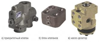
The main elements of the steering hydraulic system are a distributor, metering and cylinder pumping devices, as well as a sensor for automatically locking the rear axle of the vehicle. Considering the design of the hydraulic booster in more detail, it is necessary to mention the following important elements:
- the housing where the oil tank is located serves for mounting most of the power steering parts and elements;
- a pump that makes it possible to move oil in the hydraulic system;
- the sector in contact with the steering is located on the rotary shaft;
- rotary shaft equipped with 3 support elements;
- a rack that transmits the movement of the piston to the sector;
- a spool mounted on one of the ends of the worm gear of the steering column;
- a filter used to clean the oil circulating in the hydraulic system;
- a safety valve, the main purpose of which is to protect the unit from excessive pressure.
Be sure to read: Steering MTZ 82
If you want to know how to troubleshoot the steering column, you need to pay attention to another important design element - the automatic locking system. It is designed to lock the rear axle differential and includes several components.
Possible breakdowns
The products of the Minsk Tractor Plant are of high quality, as well as excellent technical characteristics. However, despite the long service life declared by the manufacturer, during operation of the tractor it may be necessary to repair the power steering and make a number of adjustments to the steering control unit.
Among the most common malfunctions and breakdowns:
- tight steering control;
- inability to turn the tractor steering wheel;
- the occurrence of delays in the operation of the control unit.
To fix the problem yourself, it is worth disassembling the unit and troubleshooting and adjusting individual elements, as well as replacing broken parts if necessary. After repair work, it is necessary to return the steering assembly to its place and check the quality of the repair.
Repair of the steering control of the MTZ-80 tractor
_____________________________________________________________________________
_____________________________________________________________________________
____________________________________________________________________________________________
Large free play of the steering wheel when the diesel engine is running indicates wear on the steering shaft connections, increased clearances in the meshing of the power steering gear, ball pins and steering rods, and weakening of the worm bearings on the shaft. To eliminate malfunctions of the MTZ-80 steering, check the technical condition of the steering mechanism parts and steering rods, eliminate gaps, replace parts, and adjust the mechanism. To determine the gaps in the gear and worm gears of the steering mechanism, as well as the force on the rim of the steering wheel, the NIIAT-402 device is used. The dynamometer of the device is installed on the steering wheel, and the pointer is installed on the steering column. By rotating the steering wheel in both directions until the gaps in the steering rod joints and in the engagement of the steering mechanism are eliminated, the free play of the steering wheel is determined. The nominal free play of the steering wheel corresponds to 25-30°, the permissible free play is 35°. To determine the force on the steering wheel rim, disconnect the steering rods from the bipod, start the diesel engine and, at maximum crankshaft speed, pull one of the device’s dynamometer handles. The position of the locking ring on the opposite handle determines the force of free rotation of the steering wheel. The force on the wheel rim should be in the range of 30-50 N. If the free play of the steering wheel exceeds the permissible value, adjust the power steering mechanisms. Gaps in the worm-sector gearing (Fig. 2.3.2) are eliminated by turning the adjusting sleeve 4, having previously unscrewed the locking bolt 3. If, as a result, the free play of the power steering shaft has decreased slightly, remove the housing cover (Fig. 2.3.3) and use a plate feeler gauge check the gap between the differential lock sensor (stop) and the rack (Fig. 2.3.4), which should be within 0.1-0.3 mm. The gap is adjusted by gaskets on the differential lock sensor flange (Fig. 2.3.5). Then the worm-sector engagement is adjusted again, achieving free rotation of the worm without jamming.
Rice. 2.3.2. Adjusting the gap in the worm-sector engagement by turning the adjusting sleeve 1 - dial; 2 — pointer arrow; 3 - lock bolt; 4 — worm adjusting sleeve; 5 - worm
Rice. 2.3.3. Removing the power steering housing cover MTZ-80 1 - power steering housing; 2 — power steering housing cover
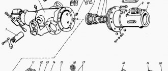
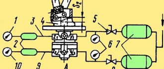
Rice. 2.3.5. Adjusting the gap in the worm-sector engagement by installing gaskets 1 - power steering housing; 2 — differential lock sensor; 3 - adjusting shims Difficulty turning the tractor indicates a lack of working fluid in the tank, a decrease in its supply, a violation of the safety valve adjustment, wear or destruction of the sealing rings of the power cylinder. Checking the technical condition of the MTZ-80 steering control hydraulic system consists of determining the flow rate, the pressure developed by the pump, oil leaks in the distributor and power cylinder, and adjusting the safety valve. All necessary measurements are carried out without removing the steering hydraulic system units from the tractor, using the KI-5473 device (throttle-flow meter). The parameters of the steering control hydraulic system are measured with a device at the nominal speed of the diesel crankshaft, a back pressure of 5.0 MPa on the device’s pressure gauge and a working fluid temperature of 50-60 ° C. The readings on the device’s flow scale are then multiplied by a correction factor of 0.7. When checking the supply of working fluid to the MTZ-80 power steering (Fig. 2.3.6), the discharge pipeline 2 is disconnected from the safety valve box and the inlet hose of the device 1 is connected to it. The drain hose is lowered into the neck 3 below the liquid level. Start the diesel engine, set the pressure to 5.0 MPa on the pressure gauge at the nominal crankshaft speed, and mark the supply of working fluid on the instrument scale. If the flow rate is below the permissible value, the pump is replaced. If the flow rate is not lower than the permissible value, the technical condition of the distributor is determined by the amount of oil leakage (Fig. 2.3.7).
Rice. 2.3.6. Checking the technical condition of the power steering high-pressure pump a - connecting the device; b - verification scheme; 1 — device KI-5473; 2 - pump discharge pipeline; 3 - power steering filler neck
Rice. 2.3.7. Determination of oil leaks in the power steering distributor MTZ-80 a - connecting the device; b - verification scheme; 1 — device KI-5473; 2 — inlet sleeve of the device; 3 — power steering filler neck; 4 - power steering distributor Main performance indicators of the MTZ-80 power steering distributor when tested with a KI-5473 device Oil supply at P = 5.0 MPa, l/min: - nominal - 2.0 - permissible - 1.2 Safety valve response pressure, MPa : - nominal - 7.5 - permissible - 7.0-8.5 To connect the inlet hose of the device, first unscrew the process plug (the plug is located on top of the safety valve box). The drain hose is connected to the hydraulic system tank. Start the diesel engine and at the rated crankshaft rotation speed, turn the steering wheel to the right or left until it stops. Having set the pressure on the pressure gauge to 5.0 MPa by rotating the handle of the device, the readings are recorded on the flow scale. If the difference in the instrument readings when checking the supply of working fluid to the distributor and checking leaks exceeds 5 l/min, the distributor is repaired. The response pressure of the safety valve of the MTZ-80 hydraulic steering system is checked with a pressure gauge, which is screwed into place of the technological plug. To check, start the diesel tractor and at the rated crankshaft speed, use the device handle to completely shut off the oil drain (with the wheels turned to the full position). Based on the pressure gauge reading, the actual pressure at which the safety valve is triggered is determined. If the response pressure is lower or higher than the permissible value, the valve is adjusted. In this case, unscrew the cap, release the locknut of the adjusting screw and, holding the steering wheel in the extreme position of rotation until it stops, screw in or out the adjusting screw until the nominal pressure is reached. Sharp jolts when turning the tractor indicate loosening of the hydraulic distributor spool nut and increased steering linkage clearances. Loosening the spool nut causes oscillations (vibration) of the front idler wheels, which is especially typical when driving at high speeds. In this case, first adjust the clearances in the steering rod joints, and then use a torque wrench to tighten the distributor spool castle nut to a torque of no more than 20 Nm and release it until the holes for the cotter pin coincide. The main defects of the MTZ-80 power steering include: wear of the worm shaft splines and sector teeth, gear rack, wear and violation of the tightness of the safety valve, wear and violation of the hydraulic tightness of precision parts (spools, plungers, sleeves). If, in the process of checking the technical condition of the units of the hydraulic steering control system of the tractor, faults are identified that cannot be eliminated by carrying out normal adjustment operations, the power steering is removed from the tractor and disassembled for technical examination and replacement of parts. The sequence of basic operations and the correct techniques for disassembling, assembling and adjusting the power steering are shown in Fig. 2.3.9—2.3.30. Before removing the power steering, drain the working fluid and unscrew the rotary shaft nut 4. When assembling the power steering, pay special attention to the tightening torques of the nuts, the correct alignment of the marks of the rotary shaft, sector and rack, and the adjustment of the vertical movement of the rotary shaft. Disassembly, assembly and adjustment operations performed during the repair of power steering are quite complex and require the use of control and testing equipment after completion of assembly. The assembled power steering is tested on the control and testing stand KI-4896M. During the tests, the free play of the steering wheel is checked with the vertical power steering shaft fixed, which should be within 4-6°, as well as the operation of the hydraulic booster under load at an input pressure of 5-6 MPa. The force on the steering wheel rim should not exceed 50 N. Fig. 2.3.10. Power steering (power steering) MTZ-80
a - general view; b - relative position of parts; 1 - amplifier housing; 2 - rail; 3 — power cylinder; 4 - piston; 5 - safety valve; 6 - spool; 7 - rotary shaft; 8 — upper cover of the power steering housing; 9 — adjusting bolt of the rotary shaft; 10 - sector; 11 — worm of the steering mechanism; 12 — differential lock sensor; 13 - drain pipe; 14 — steering bipod Fig. 2.3.9. Pressing the steering bipod 1 - attachment; 2 — steering bipod; 3 - drain pipe; 4 — rotary shaft nut Fig. 2.3.11. The relative position of the differential lock sensor parts 1, 10 - bolts; 2 - cover; 3 - spring; 4 - spool; 5 - pusher; 6 - ring; 7, 9 — housings; 8 - valve; 11— tap
Rice. 2.3.12. Removing the oil supply tube from the MTZ-80 distributor 1 - oil supply tube; 2 — power steering housing; 3 - mesh filter; 4 - pressure reducing valve
Rice. 2.3.13. Removing the rotary shaft 1 - power steering housing; 2 - rotary shaft with sector
Rice. 2.3.17. Removing the differential lock sensor cover Fig. 2.3.19. Removing the power steering hydraulic cylinder
Rice. 2.3.25. Pressing out the rotary shaft bushing 1 - bushing; 2 - axle; 3 - puller screw
_____________________________________________________________________________
__________________________________________________________________________
Service and adjustments MTZ-82
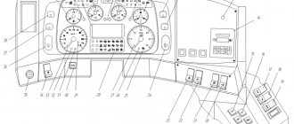
- Controls and instruments
- Working with agricultural machinery
- Maintenance of diesel engine D-243
- Clutch adjustments
- Steering
- Tractor brakes Belarus
- PTO power take-off shaft
- Front axle
- Front drive axle repair
- Hydraulic system and rear linkage
- Electrical equipment
- Maintenance
__________________________________________________________________________
Operation and service MTZ-82.1, 80.1, 80.2, 82.2
- Controls and instruments
- Gearbox and PTO control
- Rear linkage control
- Cabin elements
- Electrical components
- Clutch
- Transmission
- Gearbox and creeper control
- Reverse gearbox
- Rear axle of Belarus tractor
- Rear axle differential lock
- Rear power take-off shaft
- Tractor brakes Belarus
- Pneumatic system
- FDA with bevel wheel reducers
- FDA with planetary helical wheel reducers
- FDA drive
- Chassis system
- Hydrostatic steering
- Power steering
- Hydraulic linkage system
- Rear linkage adjustments
- Cabin Belarus
- Maintenance
- Engine Maintenance
- Transmission Maintenance
- Front drive maintenance service
- Hydraulic and steering maintenance
- Front Axle Maintenance
- Maintenance of the pneumatic system and brakes
Repair of MTZ-80
- Cylinder head repair
- Repair of piston group D-240
- Repair of fuel equipment
- Starting motor repair
- Steering repair
- Front axle repair
- Clutch and reduction gear repair
- Transmission repair
- Rear axle repair
- PTO repair
- Rear linkage hydraulic system repair
- Electrical equipment repair
Maintenance and operation of MTZ-1221
- Controls and instruments
- Transmission
- Clutch
- D-260 engine maintenance
- Rear axle
- Service brakes
- Pneumatic equipment
- PTO
- Front drive axle
- Mounted hydraulic system
- Electronic rear linkage control
- Rear linkage
- Steering
Maintenance and operation of MTZ-320
- Controls and instruments
- Diesel engine
- Clutch and gearbox
- Rear axle
- Brakes
- Rear power take-off shaft
- Front drive axle
- Steering
- Hitch and hitch
- Hydraulic system
- Electrical equipment
- Aggregation
Operation and service of tractors
- Block crankcase and crank mechanism
- Gas distribution mechanism
- Diesel engine power supply system
- Tractor engine control system
- Tractor engine cooling system
- Diesel starting system
- Tractor power transmissions
- Tractor transmission T-150, T-150K
- Drive axles of wheeled and tracked tractors
- Tractor chassis and control
- Chassis and steering of wheeled tractors
Unit repair
There are several possible scenarios for repairing the power steering unit. They depend on the type of breakdown or malfunction that occurs.
Oil leak and depressurization
The first criterion demonstrating the presence of a malfunction in the unit is the lack of tightness of the hydraulic system seals. The tightness ensures the safety of the operating pressure during operation of the unit, and also prevents changes in the magnitude of the force that acts on the amplifier organs.
If an oil leak is detected in the power steering, the following is replaced:
- oil seals;
- rings;
- gaskets that are provided with the amplifier kit.
The proper functioning of the connection of the assembly parts ensures the normal operation of the structure, preventing jamming or breakage.
Changing the working stroke
The standard spool stroke, if we consider the classic movement of the part in one direction, is 1.2 mm. This is enough to completely open the channels for the inlet and outlet of working fluid. If the stroke is disrupted and the structure deviates in any direction, the distributor ceases to cope with its function.
The result of the malfunction is the lack of a sufficient amount of working fluid in the cavity, which makes it impossible to create the required amount of hydraulic gain.
One of the reasons for such a malfunction is unacceptable backlash that occurs when assembly units are connected poorly. In total, these backlashes negatively affect the movement of the spool along the axis. Therefore, it is important to keep track of:
- The state of fastening of parts to each other.
- The size of the gaps formed in the gears.
If the backlash is adjusted incorrectly and the indicators are allowed to change, the design of the unit will quickly wear out, which will lead to breakage of the teeth, coils, and worm. If parts fail, they should be replaced with new elements.
Increasing the distance between parts
During operation, gaps between individual elements that do not require tightness may increase. Tractor drivers recommend using two methods for leveling the resulting gaps:
- Increasing the dimensions of the spool along one axis. To do this, the element is machined and special bushings-washers of suitable width are additionally machined. The diameter of the washers must correspond to the diameter of the spool recess on the inside. The improved part is installed in the assembly structure; gaskets have previously been placed to organize a sealed connection. It is noteworthy that it is precisely due to the gaskets that it is possible to compensate for the increased dimensions of the spool. To increase the rigidity of the springs holding the part, additional washers are machined, taking care of a diameter of 1.5 mm in advance, and mounted between the spool and the plungers.
- Grinding the cover fastening in order to improve its fastening to the power steering housing. In this case, it is also necessary to take care of the diameter, which will be 4 mm larger than the diameter provided for the thrust bearing race. The advantage of this method is that there is no need to install gaskets to ensure tight connections. There is also no need to cut washers for the springs.
Both methods are in demand in practice, but they are not capable of completely repairing the unit if they are installed incorrectly and all conditions for their reliable operation are not provided. If incorrectly adjusted, enlarged elements will quickly wear out and lead to power steering failure.
Malfunctions and repairs
The first criterion affecting the efficiency of the unit is the tightness of all seals of the hydraulic system, which maintain the working pressure of the fluid, providing force on the working parts. Elimination of oil leaks and pressure loss is achieved by replacing all rubber seals, O-rings and gaskets included in the complete power steering repair kit.
The serviceability of the joints of the mechanical drive, the adjustment of the engagements of the worm gearbox and the piston rack with the sector ensure the operation of the mechanism without jamming.
Adjustment
You can configure a node only if all its elements are in working order. The correct setting is determined by the factor in the form of reliable and safe operation of the amplifier while driving the tractor. The setup is carried out in several stages, and each of them is worth considering in detail.
Worm adjustment
Before making adjustments, it is necessary to check the serviceability of the steering rods and the reliability of the steering drive fastening. You should also check the free play of the steering wheel, which should not be more than 30 degrees if the engine is running. If malfunctions are found, it is necessary to eliminate them and only then resort to adjustment.
Adjustment procedure:
- First, use a jack to raise the front axle, and also dismantle the bipod, disconnecting it from the steering rods.
- Then loosen the bolt, which is responsible for the eccentricity of the sleeve.
- Twist the sleeve until it stops, ensuring maximum adhesion of the worm to the sector.
- Rotate the steering wheel to determine the engagement rate. This must be done with the engine running. Additionally, at this time, increase the clearance by continuing to rotate the bushing counterclockwise.
The final step is to tighten the bolt that secures the bushing to the assembly structure. Afterwards all that remains is to remove the tractor axle from the jack and connect the bipod to the steering rods.
Adjusting the worm nut
By turning the worm nut, it is possible to level the gap that occurs between two elements: the cages and the spool. The gap appears due to power steering exhaustion or weakening of the fastening element. The larger the gap, the worse the free steering control, and in the end such a malfunction can lead to breakdown of the unit.
The adjustment occurs as follows:
- First, dismantle the assembly housing cover by unscrewing the bolts.
- Next, the distributor is secured using two bolts, which must be positioned diagonally on the housing. In this case, the thickness of the cover flange is restored using backings made of washers or nuts.
- The third step is to tighten the adjusting nut. It will be pinned until the spool rests against the races provided in the bearings.
- Then turn the spherical nut of the structure until it coincides with the hole that is located on the shaft. When this happens, the nut is tightened.
- Remove the installation bolts, which were secured with washers, and return the cover to its place, additionally providing for replacing the gasket.
- The four cover mounting bolts are screwed back in.
With the help of proper tightening, it is possible to ensure a tight fit of the spool to the surface of the races provided in the bearings. Thus, the element returns to the neutral position when turning is stopped, and the gap between the parts disappears. It is worth noting that it is not recommended to overtighten structural elements, as this may lead to wear.
Adjusting the spool stroke
To adjust the spool stroke, it is necessary to use gaskets that are installed between:
- Distributor and amplifier housing.
- The distributor and the surface of the spherical nut cover.
If turning to the left requires additional effort from the tractor driver, then you will need to install another gasket, the thickness of which should be in the range from 0.5 to 1 mm. It is mounted in the space between the column and the distributor. In cases where it is not possible to ensure normal rotation to the right, a gasket is installed under the nut cover in the shape of a sphere. Due to this adjustment, it is possible to align the movement of the part.
When the adjustment is completed, you will need to check the pressure in the system and tighten a number of nuts and springs if the pressure indicator is not enough. Operation of the MTZ-80 requires a responsible approach and regular diagnostics of the power steering unit.
Not available:
| № | Part code | Name | Part Information |
| 85-3401010 | Steering column for metering pump ND-80 and instrument panel 80-3805010 assembled | Quantity 1 Model 85 Group Steering control Subgroup Steering control (steering mechanism) Part number 010 | Not available |
| 85-3401150 | Cardan assembly for OSPB-100 | Quantity 1 Model 85 Group Steering control Subgroup Steering control (steering mechanism) Part number 150 | Not available |
| 85-3401120 | bracket | Quantity 1 Model 85 Group Steering control Subgroup Steering control (steering mechanism) Part number 120 | Not available |
| 85-3401016 | Sleeve | Quantity 1 Model 85 Group Steering control Subgroup Steering control (steering mechanism) Part number 016 | Not available |
| S20 | Ring | Quantity 1 | Not available |
| 80-3401019 | Washer | Quantity 1 Model 80 Group Steering control Subgroup Steering control (steering mechanism) Part number 019 | Not available |
| 85-3401156-B | Plug (OSPB-100) | Quantity 1 Model 85 Group Steering control Subgroup Steering control (steering mechanism) Serial number of the part 156 Additionally Interchangeable with the part released earlier under the same number | Not available |
| C19 | Ring | Quantity 8 | Not available |
| 50-3401064 | Stuffing box | Quantity 8 Model 50 Group Steering control Subgroup Steering control (steering mechanism) Part number 064 | Not available |
| 50-3401063 | Clip | Quantity 8 Model 50 Group Steering control Subgroup Steering control (steering mechanism) Part serial number 063 | Not available |
| M10 | screw | Quantity 1 | Not available |
| 80-3401013 | Washer | Quantity 2 Model 80 Group Steering control Subgroup Steering control (steering mechanism) Part number 013 | Not available |
| 50-3401061-A | Fork | Quantity 1 Model 50 Group Steering control Subgroup Steering control (steering mechanism) Part serial number 061 Additionally Interchangeable with a part previously released under the same number | Not available |
| M10×45 | Bolt | Quantity 1 | Not available |
| 5×10 | Hose | Quantity 1 | Not available |
| 70-3401050-B | Shaft with pin and shank assembly | Quantity 1 Model 70 Group Steering control Subgroup Steering control (steering mechanism) Part serial number 050 Additionally Interchangeable with a part previously released under the same number | Not available |
| 70-3401055 | Intermediate shaft | Quantity 1 Model 70 Group Steering control Subgroup Steering control (steering mechanism) Part serial number 055 | Not available |
| 70-3401054-B | Shaft shank | Quantity 1 Model 70 Group Steering control Subgroup Steering control (steering mechanism) Serial part number 054 Additionally Interchangeable with a part previously released under the same number | Not available |
| ШЦК8х36 | Pin | Quantity 1 | Not available |
| 70-3401077-B | Shock absorber | Quantity 2 Model 70 Group Steering control Subgroup Steering control (steering mechanism) Serial part number 077 Additionally Interchangeable with a part previously released under the same number | Not available |
| 70-3401076 | Sleeve | Quantity 2 Model 70 Group Steering control Subgroup Steering control (steering mechanism) Part serial number 076 | Not available |
| 70-3401078 | screw | Quantity 1 Model 70 Group Steering control Subgroup Steering control (steering mechanism) Part number 078 | Not available |
| 70-3401079 | Lock-nut | Quantity 1 Model 70 Group Steering control Subgroup Steering control (steering mechanism) Part number 079 | Not available |
| 80-3401082 | Head cover | Quantity 1 Model 80 Group Steering control Subgroup Steering control (steering mechanism) Part number 082 | Not available |
| 80-3401140 | Clamp | Quantity 1 Model 80 Group Steering control Subgroup Steering control (steering mechanism) Part number 140 | Not available |
| M16x1.5 | screw | Quantity 1 | Not available |
| 50-3401091 | Washer | Quantity 1 Model 50 Group Steering control Subgroup Steering control (steering mechanism) Part number 091 | Not available |
| 80-3402015 | Wheel | Quantity 1 Model 80 Group Steering control Subgroup Steering wheel Part serial number 015 | Not available |
| 80-3709025 | Sleeve | Quantity 1 Model 80 Group Electrical equipment Subgroup Electrical switches (central light switch) Part number 025 | Not available |
| 80-3709026-B | Sleeve | Quantity 1 Model 80 Group Electrical equipment Subgroup Electrical switches (central light switch) Part serial number 026 Additionally Interchangeable with a part previously released under the same number | Not available |
| 80-3709024 | Case | Quantity 1 Model 80 Group Electrical equipment Subgroup Electrical switches (central light switch) Part number 024 | Not available |
| 50-4608057 | Spring | Quantity 1 Model 50 Subgroup 4608 Part number 057 | Not available |
| 85-3401175 | Shaft | Quantity 1 Model 85 Group Steering control Subgroup Steering control (steering mechanism) Part number 175 | Not available |
| 600-3401012 | Washer | Quantity 1 Model 600 Group Steering control Subgroup Steering control (steering mechanism) Part number 012 | Not available |
| 70-3003032 | screw | Quantity 2 Model 70 Group Steering rods. Front and rear axles Subgroup Steering rods Part number 032 | Not available |
| 8×28 | Rivet | Quantity 2 | Not available |
| 600-3401160 | Sector | Quantity 1 Model 600 Group Steering control Subgroup Steering control (steering mechanism) Part number 160 | Not available |
| 50-3401062 | Cross | Quantity 2 Model 50 Group Steering control Subgroup Steering control (steering mechanism) Part number 062 | Not available |
| 85-3401067 | Fork | Quantity 1 Model 85 Group Steering control Subgroup Steering control (steering mechanism) Part number 067 | Not available |
| 70-3709012-A | Switch handle | Quantity 1 Model 70 Group Electrical equipment Subgroup Electrical switches (central light switch) Serial part number 012 Additionally Interchangeable with a part previously released under the same number | Not available |
| 4×25 | Cotter pin | Quantity 2 | Not available |
| 85-3401011 | Screw | Quantity 2 Model 85 Group Steering control Subgroup Steering control (steering mechanism) Part number 011 | Not available |
| 80-3401001 | Traction | Quantity 1 Model 80 Group Steering control Subgroup Steering control (steering mechanism) Part number 001 | Not available |
| 50-1310158-B | Spring | Quantity 1 Model 50 Group Cooling system Subgroup Radiator shutters Serial part number 158 Additionally Interchangeable with a part previously released under the same number | Not available |
| 1,6×12 | Cotter pin | Quantity 1 | Not available |
| C18 | Ring | Quantity 1 | Not available |
| 85-3401014 | Retainer | Quantity 1 Model 85 Group Steering control Subgroup Steering control (steering mechanism) Part number 014 | Not available |
| 822-3401140-A1 | Clamp | Quantity 1 Model 822 Group Steering control Subgroup Steering control (steering mechanism) Part serial number 140 Additionally Interchangeable with a part previously released under the same number | Not available |
| ShP16 | Washer | Quantity 1 | Not available |
| 70-3402015-A | Steering wheel | Quantity 1 Model 70 Group Steering control Subgroup Steering wheel Serial part number 015 Additionally Interchangeable with a part previously released under the same number | Not available |