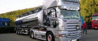
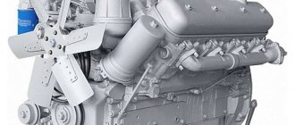
Scania 113 is a Swedish tractor, one of the most common models among truck tractors in the Scania model range. During the years of production, the machine was in high demand, and today it is very popular in the supported market - due to its low cost and balanced characteristics. The presentation of the model took place in 1988 at the Geneva Motor Show. The car received two modifications that differ in wheel arrangement - 4x2 and 6x2. In the first case, the cardan is synchronized between the gearbox and the rear axle gearbox, and in the three-axle version, the cardan is also connected to the second and third axles. The approximate cost of the model is 10 thousand dollars.
Scania G420 2 doors tractor manual transmission, - increased fuel consumption
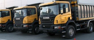
Scania models meet the most stringent international quality standards. During the tests, it was found that the truck’s cabin is characterized by increased safety, which is extremely important in emergency situations. The interior of the dump truck deserves special mention, because in addition to the high functionality of the dashboard, it is distinguished by increased comfort, surpassing the indicators of domestic KamAZs and French Renaults.
The dump truck from Scania is characterized by increased rigidity of the body elements, which helps to avoid future deformation. The cabin and body are not thermally insulated, but some models have underbody heating. Scania trucks are equipped with standard equipment:
- retractable awning;
- holder that secures the spare wheel;
- visor protecting the hydraulic cylinder.
The Scania model range is quite diverse. The models have engines of varying power - from 220 to 620 horsepower. Most models have a 12-speed transmission.
As an example, consider the technical characteristics of the P 380CB model:
| Curb weight | 13 tons |
| total weight | 39,000 kg |
| body volume | 16 cubic meters |
| engine model | Scania DC11 |
| engine's type | turbodiesel |
| cylinder volume | 10,640 cubic centimeters |
| power indicator | 380 hp |
Change of oil
- engine oil is removed;
- the oil filter is replaced;
- The sealing washer is replaced and the magnet is cleaned. Oil is poured in accordance with the specified values for filling volumes.
Refill capacity
| Engine model | Volume |
| 5 cylinder engine | 30-37 liters |
| 9 liter engine | 23-30 liters |
| 11 liter engine with two valves per cylinder | 23-30 liters |
| 11 and 12 liter engine with four valves per cylinder | 28-35 liters |
| 14 liter engine | 22-30 liters |
| 16 liter engine | 26-32 liters |
Note: It is imperative to check the filled oil level with an oil dipstick - the indicated values are approximate. If necessary, add oil to normal level.
The oil dipstick should move freely along the guide tube, without jamming. To do this, it is installed in the correct position.
Important! The viscosity properties of the oil used must correspond to the ambient temperature ranges expected before the next oil change.
We recommend
Maybe the air filter, maybe the turbine, maybe the exhaust brake flap, maybe the muffler, maybe the intercooler, maybe the boost and air temperature sensor, maybe the problem is in the trailer that it is more difficult to drag, or in the chassis of the tractor. To be brief, all problems, as usual, occur due to the low quality of our diesel fuel, namely due to the high sulfur content in Russian diesel fuel.
Replacing the oil pump filter element
- The socket 588 475 is used to remove the filter cover.
- When the filter element is removed, the oil will drain from the housing automatically.
- The O-ring on the filter cover is replaced. The new ring is lubricated with engine oil.
Important! To avoid damage to the filter element, lower it into the filter housing only after it has been inserted into the cover.
- After installing the filter element, previously inserted into the cover, in the filter housing, the cover is tightened with a force of 25 N∙m ± 5 N∙m.
Main symptoms of Scania injector failure • Oil filters
| Scania HPI high fuel consumption, example of a malfunction and temporary repair. For Scania vans operating without taking into account the weight of the transported cargo, the normalized value of fuel consumption is determined taking into account an increasing correction factor of up to 10 to the base standard. From the suction filter, fuel enters the control unit cooler through fuel line 2, and then from the control unit cooler is supplied to the booster pump through fuel line 3. |
| Evolution of the SCANIA fuel system - Forum of truck owners Scania, Volvo, Man, Daf, Mercedes, Iveco This complex system is constantly reconfigured, adapting to changes in speed and various situations, so that not a single drop of diesel is wasted. Interesting, today I will show you how to return the hpi system to almost factory operation, it will take a couple of minutes and the pleasure of driving after that will be indescribable, I experienced it, I hope you subscribe. |
- Remove the tailgate. When a semi-trailer drives empty, air currents hit its rear side. A vortex occurs, and the tractor-trailer experiences additional aerodynamic drag. To remove this load on the fuel system, simply remove or open the rear borer.
Centrifugal type oil purifier
Cleaning mechanism design
Instructions for the old version of the mechanism design
The design option (new or old) is preliminarily determined and then according to the instructions:
- The fastening nut is unscrewed and the cover is removed, first cleaning it.
The rotor is removed. Unscrew the rotor nut three turns.
If difficulties arise, the nut must be clamped in a vice. The rotor must not be clamped in a vice! Manually or using a tool, turn the rotor three turns.
By lightly tapping the nut (you can tap it with your hand or with a plastic hammer), you can separate the rotor from the base.
The nut is unscrewed and the rotor housing is removed. Carefully remove the mesh filter from the base.
The plaque formed on the inner surface of the rotor is removed mechanically. Considering that when the deposit thickness is more than 25 mm, the frequency of maintenance of the centrifugal oil purifier must be increased.
The removed parts are washed in diesel fuel.
The condition of the sealing ring is checked - it should not be damaged. The ring is installed in the rotor housing.
The rotor nut is tightened by hand.
The rotor is installed in place, and it is checked whether the part rotates easily.
The condition of the sealing ring of the purifier cover is checked - it should not be damaged. The cover is put in place. The fastening nut is tightened with a force of 10 N∙m.
Scania HPI high fuel consumption, example of a malfunction and temporary repair.
Scania HPI high fuel consumption, example of a malfunction and temporary repair. In this video I will talk about a typical malfunction of HPI scan motors. About wear of fuel supply valves and injection deflection valves.
Jahongir Qodirov
4 months ago
sarco
6 months ago
Interesting, today I will show you how to return the hpi system to almost factory operation, it will take a couple of minutes and the pleasure of driving after that will be indescribable, I experienced it, I hope you subscribe!)
Slava //\\
6 months ago
If the actuator passes more fuel, then the injection will not be late, but rather early 1.48 minute video
Mikhail Chebunin
6 months ago
Alexey, good morning, on the r450 xpi 2013 with all the original EGR and other amenities, fuel consumption suddenly increased by 10-15% with a mileage of 850,000 km. Would you recommend that we pay attention and check first? The other day we replaced the injector with an original one from the officials, as they discovered a pressure leak of about 400 instead of 300, which seems to be acceptable. Could this be related?
Sergey Rusetsky
7 months ago
There is an inconsistency with you (I hope you made a mistake) I am a simple driver, but the r420 with npi forced me to study it seriously. And so you said (advanced actuators provide more fuel - I agree, but at the same time the injection will be earlier, won’t it? You made a reservation. We are not talking about the moment of opening of the advance actuator now.
Marat Yapparov
8 months ago
Alexey, please tell me. How can I contact you by phone? Need some advice.
Ilhomjon Uktamov
9 months ago
Arthur Kasparov
10 months ago
124 Hpi year of manufacture 2003. Consumption was in the range of 29-31 loads. Empty 23-26. Over the last 30,000 thousand mileage it began to vary 37-42. Is there any meaning to this action? Instant consumption 1.6 2.0. Or prepare money to purchase valves? PS I will be grateful for your answer.
Anatoly Robkov
10 months ago
We repaired the actuators, and the rpms began to fluctuate, the technicians who did the work are telling me that I installed it wrong, something got into the fuel, etc., etc., before the repair the engine was running smoothly without interruptions, but the consumption was high, according to the computer it was 27 liters, in fact 37, how to prove to them that their hands are growing out of their ass, I paid 46 ts for repairs, and I look in the mirror and see a sucker.
Name Surname
10 months ago
What should be the consumption on a scan after a million miles?
Skobar on the Bench
10 months ago
Hello. Scania hpi R420 tell me where to go for fuel diagnostics in St. Petersburg. So as not to get scammed. And they helped. It's hard to start when cold, it won't work,
Andrey Lesko
10 months ago
My car charges a lot for 40l. then it takes a little 28l. 4 episode 2004.hpi
temik tuktar
11 months ago
One actuator costs 130
11 months ago
You can't regulate it like that. You will ruin the valves. One original valve costs 70-90 thousand!! Multiply them 4!! They are adjusted only at the stand. Get in once and you'll be fucked for the rest of your life!!
Eugene
1 year ago
When you turn it up, add fuel or reduce it
1 year ago
I have 0.7.08 is this the norm or is it better to adjust the flow rate from 20t 32-34
Anatoly Ivagov
1 year ago
Alexey, tell me the hpi and pde camshafts are different?
sonic.rf
1 year ago
I'll tell you my story. Consumption has increased greatly. I went to the service center, removed and cleaned these valves, washed the injectors, drove off, and after 50 km the problem returned. I’m scratching my turnips, and if I don’t give it more than a fuel consumption of 40 liters per hundred square kilometers, the car will run. As soon as the first slightest excess of this parameter, the consumption increases significantly to 150-300 liters. Pillar of smoke. It turned out to be the fuel filter. I changed it and went.
The procedure for adjusting valves on a 9 liter Scania 93 engine
This is what the 9 liter engine of a Scania 3-series car looks like.
Adjustment of clearances must be carried out on a cold engine.
The operating order of the cylinders is 1-5-3-6-2-4
Valve clearances: intake valve = 0.45 mm exhaust valve = 0.80 mm
Before adjustment, we recommend checking the tightening of the rocker shaft to a torque of 150 Nm.
1 turn. Turn the flywheel to the TDC mark. The first cylinder must be exactly at TDC; the compression cycle has ended in this cylinder. That is, both valves must be closed.
- We adjust valves for the following cylinders:
- 1 cylinder we adjust both intake and exhaust valves;
- 2nd cylinder intake;
- 3 exhaust cylinder;
- 4 cylinder intake;
- 5 exhaust cylinder;
- 6 cylinder is not adjustable.
After adjustment, tighten the nuts of the rocker arm screws to a torque of 40 Nm.
2 turns Turn the flywheel to the TDC mark. The sixth cylinder must be exactly at TDC; the compression cycle has ended in this cylinder. That is, both valves must be closed.
- We adjust valves for the following cylinders:
- 6 cylinder we adjust both intake and exhaust valves;
- 5 cylinder intake;
- 4 exhaust cylinder;
- 3 cylinder intake;
- 2 exhaust cylinder;
- 1 cylinder we do not adjust anything.
After adjustment, tighten the nuts of the rocker arm screws to a torque of 40 Nm.
We recommend. Anatoly Ivagov
| Scania HPI high fuel consumption, example of a malfunction and temporary repair. watch video| The engine control unit processes both signals from sensors and devices included in the EDC system, as well as data received from control units of other vehicle systems. If malfunctions in the operation of these parts are identified, it is recommended that you first contact specialized services that have the appropriate equipment, since in any situation repairs are preceded by detailed diagnostics. |
| Pde or hpi which is better. On my machine at 2000 rpm 17 points, that’s 240psi, at 1500 rpm 16 points before the filter, after the filter the pressure naturally drops by about 1 point. The control unit processes signals both from sensors and devices included in the EDC system, as well as data received from control units of other vehicle systems. |
Repair kits for pump injectors • The tightness of the valve can be damaged by mechanical particles contained in insufficiently high-quality fuel; in high-quality fuel, they are negligible.
The procedure for adjusting valves on a 14 liter Scania 143 engine
This is what the 14 liter engine of a Scania 3-series car looks like.
Adjustment of clearances must be carried out on a cold engine.
The operating order of the cylinders is 1-5-4-2-6-3-7-8
Valve clearances: intake valve = 0.45 mm exhaust valve = 0.80 mm
The arrangement of the cylinders of the 14 liter engine of the Scania 3-series car.
Stage 1. Set the piston of cylinder 1 to a position of 30° after TDC after the power stroke. This position is indicated by a mark on the flywheel.
- We adjust valves for the following cylinders:
- 1 cylinder we adjust both intake and exhaust valves;
- 2 exhaust cylinder;
- 3 cylinder we do not adjust anything
- 4 exhaust cylinder;
- 5 cylinder we adjust both intake and exhaust valves;
- 6 cylinder we do not adjust anything
- 7 cylinder intake;
- 8 cylinder intake.
Stage 2. Turn the crankshaft exactly one revolution. Set the flywheel to a position 30° after TDC. 1 cylinder on the intake stroke. This position is indicated by a mark on the flywheel (see illustration).
- We adjust valves for the following cylinders:
- 1 cylinder we do not adjust anything
- 2nd cylinder intake;
- 3 cylinder we adjust both intake and exhaust valves;
- 4 cylinder intake;
- 5 cylinder we do not adjust anything
- 6 cylinder we adjust both intake and exhaust valves;
- 7 graduation;
- 8 graduation.
Source
—>Catalog of service manuals (technical documentation for the repair of commercial equipment) —>
Basic information Identifying faults in the Scania HPI fuel system, symptoms of which include, for example, vibrations, black smoke, reduced power or increased fuel consumption, has proven to be a difficult task. In addition, these symptoms cannot always be associated with malfunctions in the SCANIA power system. The supply system is divided into high and low pressure sections. The low pressure section is designed to supply fuel from the fuel tank to the solenoid valves, which in turn provide fuel to the pump injectors. There must be no air in the fuel and it must be at the correct pressure. These two conditions are important and their fulfillment should be monitored primarily when troubleshooting.
Attention! Scania Diagnos cannot detect a fault in an individual pump injector
troubleshooting
A – The engine does not start, runs poorly, starts with difficulty, has reduced power. Start the engine or crank the crankshaft with the starter, performing the following checks. A1 – The fuel pressure in the valve body is correct 1. Check for the absence of air in the engine supply system 2. Check the valve clearance and injector closing force 3. Check the gaskets and injector seat in the cylinder head A2 – The fuel pressure in the fuel filter housing is correct 1. Check the fuel filter to ensure that it is not clogged 2. Check the opening of the fuel shut-off valve A3 – The fuel pressure in the fuel filter housing is correct 1. Clean the bypass valves in the valve housing A4 – The fuel pressure in the fuel filter housing is incorrect 1. Check the drain from the fuel filter housing 2 . Clean the bypass valve in the fuel filter housing 3. Check the booster pump
B – White exhaust smoke after starting Attention! If the temperature is below -5°C, check the fuel for wax deposition. B1 – Ventilation valve is faulty. Replace the vent valve. B2 - White smoke from the front or rear bank of cylinders 1. Temporarily swap the solenoid valves between the front and rear banks of cylinders 2. If the fault follows the solenoid valve, replace it B3 - White smoke from all cylinders. Look for the fault outside the Scania HPI power system.
C – Difficulty turning off the engine
C1 – Leakage. Check the sealing plugs of injector C2 – there are no leaks. Look for the fault outside the Scania HPI power system. C3 – Leakage. Overhaul injector D – Difficulty starting the engine after a long period of inactivity. Check the fuel tank fittings check valve
Checking the fuel pressure in the valve body Important! Do not operate the starter for more than 20 seconds during one attempt. Start the engine or turn the crankshaft with the starter. Use Scania Diagnos to check the fuel pressure in the valve body. Compare the result with Graph 1 or 2. If the supply pressure is between the upper and lower limits, no DTC is recorded, i.e. the fuel pressure is OK.
The procedure for adjusting valves on an 11 liter Scania 113 engine
This is what the 11 liter engine of a Scania 3-series car looks like.
Adjustment of clearances must be carried out on a cold engine.
The operating order of the cylinders is 1-5-3-6-2-4
Valve clearances: intake valve = 0.45 mm exhaust valve = 0.80 mm
Before adjustment, we recommend checking the tightness of the rocker arm axle bolts to a torque of 84 Nm. Since the outer bolts are also fastenings for the valve covers and can become unscrewed during dismantling.
The procedure for adjusting the valves of an 11 liter engine is the same as the procedure for adjusting the 9 liter engine. After adjustment, tighten the nuts of the rocker arm screws to a torque of 40 Nm.
Description, technical characteristics and owner reviews - Purpose and advantages
| Scania CNG: natural gas truck. Real Savings Figures and Operating Experience 4171 is SCR - Nitrogen Oxides NOx After Catalytic Converter Description The measured amount of nitrogen oxides is different from what it should be. If the car is moving, then the driver presses the gas deeper to drive at the same speed in order to compensate for the parasitic work of the burning fuel due to early injection. |
- A gas truck filled with methane should not be idle for more than 5 days at a liquefied methane pressure of 10 bar. Increased pressure to 14 bar reduces the downtime to one day. Exceeding these standards will lead to gas leakage into the atmosphere through the safety valve.
- In cold weather the starter may fail. The throttle valve does not always withstand low temperatures. It is enough to warm up the pipe with a hairdryer - and the problem is solved.
- Repairing trucks using gas engine fuel requires a careful approach. Otherwise, liquefied methane may leak, which will lead to low-temperature burns.
- The truck must be grounded when refueling. A completely emptied cryotank, as well as connecting hoses, must be purged. During the filling process, it is better not to touch the filling hose.
Basic version of Scania Opticruise with limited functionality Design features
Also, the new freight vehicles were tested on local roads, where on a road section of up to 70 kilometers, at a speed of 63 kilometers per hour, the vehicle processes within 38 liters of fuel fluid per hundred kilometers. at 1900 rpm maximum torque of 2100 Nm at 1100 1350 rpm, which is equipped with the R 420 truck tractor, is based on the previously produced DT 12 HPI Euro 3 turbocompound diesel engine with a power of 470 hp.
| Manufacturer: | Scania AB (Sweden) |
| Model: | Scania R 420 LA4x2 HNA CR19 |
| Start of sales in Russia: | 2010 |
Cost of installation and equipment
The cost depends on the type of vehicle and the composition of the equipment. For example, if you want to increase the range and add additional cylinders, the cost will be higher.
Thanks to the program of our partners Gazprom Gas Engine Fuel, you can get methane equipment for free, you only need to pay for the installation work
To participate, you need to submit documents for approval - an enterprise card on which the transport is registered and scans of the vehicle title.
Conditions of participation - for re-equipment at the expense of Gazprom, you enter into a contract for 3 years, under which you are obliged to consume a specified volume of gas*: for a mainline tractor this is 3492 m3/month . The volume depends on the cost of equipment, which is compensated by Gazprom. The volume depends on the cost of equipment, which is compensated by Gazprom. If the cost of a set of equipment is higher than the compensation limits, for example, you wanted to supply more cylinders, then you simply pay the difference.
*For every 1 m³ of gas not consumed, you need to pay 7 ₽ for equipment rental. For example, you did not consume 100 m³ of the established limit, which means you need to pay 700 ₽.
RUB 490,000 Cost of re-equipment of a mainline tractor
440,000 rubles The cost of equipment is paid by Gazprom
50,000 rubles You pay the cost of installation
A few words about
The Swedish company Scania was founded in 1891. Over more than a century of history, more than 1,400 thousand trucks and buses have rolled off its assembly lines, currently used in all countries of the world.
Today Scania is one of the largest manufacturers of trucks and buses. Another important area of its activity is the manufacture of industrial and marine diesel engines. The company directs all resources to the development of production; this is its main difference from similar automakers.
Scania is not afraid of economic crises: as practice has shown, even in difficult years for truck manufacturers, the Swedish giant has always received high profits. Scania means reliability and quality of diesel engines in all corners of the globe, even in the most adverse conditions!
In addition to Sweden, the concern's production facilities are currently based in countries such as France, the Netherlands, Argentina, Brazil, Poland, and Russia. There are 11 Scania factories in total. Their products received the prestigious international “Truck of the Year” awards in 2004 and 2009.
Diesel engines with the Scania logo fully meet all modern environmental requirements. Currently they are equipped with high-tech unit injectors from Cummins and Bosch.
Air purifier
The air entering the air purifier is cleaned of dust particles using a paper filter element. Air enters through the side opening, then the air passes through the filter element and is directed to the inlet of the turbocharger compressor through the upper opening in the housing.
Water that gets into the air cleaner housing along with the air accumulates near the drain valve. The valve is rubber; water is removed from the body at the moment when its pressure on the valve exceeds the pressure of the outside air. The valve opens and water is removed.
The air filter is replaced after dismantling the right section of the bumper. This section is secured with 3 screws. On cars with a steel bumper, replacing the air filter occurs differently.
The air cleaner cover is secured with spring clips.
The housing must be removed and a new filter element installed.
Vacuum indicator
Location of the vacuum indicator:
| Cabin type | Indicator location |
| P/R | On the right side of the cab behind the step guard |
| T | Behind the right service step |
A drop in engine power may be due to insufficient air entering the engine. The reason is severe contamination of the filter. When the driver presses the accelerator pedal in order to compensate for the drop in power, it leads to a decrease in the fuel efficiency of the internal combustion engine. In addition, the soot content in the exhaust gases increases. Another risk is possible turbocharger failure.
The indicator has two windows on its body. A smaller window may change color. This is a signal that the filter element needs to be replaced. The second window, which is larger in size, has a scale by which you can determine the amount of vacuum. The filter element must be replaced when the vacuum value is ≥ 5.0 kPa.
Adjusting valve clearances (six-cylinder internal combustion engine with a displacement of 9, 11 and 12 l)
Note: To check and adjust, the internal combustion engine must be cold.
Valve clearance values:
| Engine displacement, l | Gap size, mm |
| 9, 11 (except DC11) | Intake – 0.45 Exhaust – 0.80 |
| DC9, DC11, ICE 12 l | Intake – 0.45 Exhaust – 0.70 |
Ways to adjust gaps
You can use one of the following methods to adjust the gaps.
The required piston is installed at Top Dead Center (TDC - end of compression stroke, TDC mark). The clearances of the intake and exhaust valves are adjusted. Using tool 99 309, the crankshaft is rotated 1/3 of a full revolution, after which it moves to the next cylinder. The valve clearances are adjusted in the order corresponding to the operation of the internal combustion engine cylinders: 1 – 5 – 3 – 6 – 2 – 4.
- The piston of the 1st cylinder is installed at Top Dead Center (TDC). The valves are adjusted:
| Cylinder | Valves |
| 1 | Inlet and outlet |
| 2 | Intake |
| 3 | Intake |
| 4 | Intake |
| 5 | Graduation |
- A full rotation of the crankshaft is made. The valves are adjusted:
| Cylinder | Valves |
| 2 | Graduation |
| 3 | Intake |
| 4 | Graduation |
| 5 | Intake |
| 6 | Inlet and outlet |
Adjusting valve clearances in internal combustion engines with a displacement of 14 and 16 liters
Note: To check and adjust, the internal combustion engine must be cold.
Valve clearance values:
| Engine displacement, l | Gap size, mm |
| 14 | Intake – 0.45 Exhaust – 0.80 |
| 16 | Intake – 0.45 Exhaust – 0.70 |
ICE with a displacement of 14 liters
To adjust the gaps, use one of the methods below.
- The piston of the 1st cylinder is installed at Top Dead Center (TDC - end of the compression stroke, TDC mark).
- The clearances of the intake and exhaust valves are adjusted.
- Using tool 99 309, the crankshaft rotates 1/4 of a full revolution, after which you can move on to the next cylinder.
- The valve clearances are adjusted in the order corresponding to the operation of the internal combustion engine cylinders: 1 – 5 – 4 – 2 – 6 – 3 – 7 – 8.
- The crankshaft is turned in the direction of rotation so that the piston of the 1st cylinder is at the 20° position after passing the TDC (Top Dead Center) mark. On the flywheel this position is marked ┴.
- The valves are adjusted:
| Cylinder/Row | Valves |
| 1/Right | Inlet and outlet |
| 2/Right | Graduation |
| 4/Right | Graduation |
| 5/Left | Inlet and outlet |
| 7/Left | Intake |
| 8/Left | Intake |
- One full revolution of the crankshaft is made in the direction of rotation. The piston of the 1st cylinder is set at the 20° position after passing the TDC (Top Dead Center) mark on the intake stroke.
- The valves are adjusted:
| Cylinder/Row | Valves |
| 2/Right | Intake |
| 3/Right | Inlet and outlet |
| 4/Right | Intake |
| 6/Left | Inlet and outlet |
| 7/Left | Graduation |
| 8/Left | Graduation |
ICE with a displacement of 16 liters
The crankshaft is rotated using tool 99 309, and adjustments are made using the corresponding mark. The mark should be visible in the lower window of the casing:
| Marker, degree indicator | Cylinder No. – valve overlap | Adjusting the intake valves on the cylinder | Adjusting the exhaust valves on the cylinder |
| 0º, compression | 6 | 7, 8 | 4, 5 |
| 180º, inlet | 7 | 1, 5 | 2, 6 |
| 360º, compression | 1 | 2, 4 | 3, 7 |
| 540º, intake | 4 | 3, 6 | 1, 8 |
Recommendation: in order to simplify control over the valve adjustment, mark the valve rocker arms after completing their adjustment.
After completing the adjustment work, the locknuts of the adjusting screws are tightened with a force of 35 N∙m.
Checking the ridge belt tension
Automatic ripple belt tensioner
It is not allowed to make changes to the design of the automatic tensioner (tensioner), disassemble it, or attempt to make repairs or adjustments. The tensioner should be replaced if the device no longer provides the required tension on the ridge belt.
The noise level from the belt drive has increased
In this case, it is necessary to check the operation of the tensioner. It must be slowly moved away from the ripple belt until it stops, then also carefully returned to its original position. The operation must be repeated up to three times. Do not allow jerking or jamming in the operation of the tensioner.
Taking measurements
Recommendations for the tension force of rip belts type FO
| New belt | 370 N∙m |
| Belt used | 310 N∙m |
The higher stiffness of new belts means that more tension is required.

