» Power transmission » Front drive axle of the T-40 tractor - design and repair
Front axle device
The front drive axle of the T-40 AM and T-40 ANM tractors is used to increase traction forces and increase cross-country ability on moist soils and in off-road conditions. The front axle consists of a transfer case, differential, main and final gears and suspension.
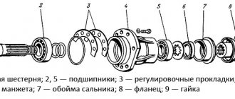
Diagram of the T-40 front axle: 1 - transfer case housing; 2 - plug; 3 - gear; 4, 24 — ball bearings: 5 — front cover; 6 — transfer case shaft; 7 — drive shaft of the front drive axle; 8 — main gear drive shaft; 9 - drive gear; 10 - glass; 11 — driven gear; 12 — adjusting shims; 13 - wedge; 14 — axle shaft; 15 — brake washer; 16 — bridge body; 17 — pawl axis; 18 - dog; 19 — differential housing cover; 20 — shield; 21 — final drive; 22 — front wheel suspension; 23 — cardan; 25 — splined holder; 26 — differential housing; 27 - pin; 28 — sleeve.
Front axle final drive
The main gear consists of a pair of bevel gears with a circular tooth. The drive gear is mounted in a cup on two ball bearings. The driven gear is part of the differential and is attached to the differential housing with bolts and pins.
During operation of the front axle, it is necessary to monitor the lateral clearance in the engagement of the teeth of the main gear. If noise or other malfunctions occur, it is necessary to check the mesh clearance or axial play of the drive gear.
Due to tooth wear, an increase in the lateral clearance in the meshing is permissible up to 2 millimeters. If the gap increases due to wear of the bearing tracks, they must be replaced with new ones.
The factory adjustment of the lateral clearance in the gear mesh is in the range of 0.17-0.65 mm.
Both gears are replaced simultaneously during operation and further development of their service life. When installing the sleeves, the total number of shims on both sides should be such that the differential rotates freely in the bearings by hand without any jamming or displacement.
Front axle differential
The differential allows the drive wheels to rotate at the same angular speed, which is required when driving the tractor over uneven terrain and when performing maneuvers.
The front drive axle differential design is a double-acting ratchet-type overrunning clutch. The differential consists of a housing, a splined race, a driven gear and a cover, connected to each other using four bolts.
In the driven gear, cover and differential housing there are two axes each, on which a pawl is installed on a key.
As the driven gear rotates, the pawls engage with the inner races by the frictional force that appears between the special patterns on the ends of the pawl axles and the surfaces of the brake washers.
Using springs, the axles are constantly pressed against the brake washers to create friction. Depending on the direction of rotation, the pawl engages with one of its ends. If the rear wheels rotate with less than 4% slip, the splined races overtake the driven gear, forcing the pawls to click along the teeth of the races.
When the slipping of the rear wheels exceeds 4%, the forward movement of the tractor will decrease, while the driven gears and angular speeds of the cage will be leveled.
With a subsequent increase in slipping of the rear wheels, the pawls will engage with the splined race, as a result of which torque will be transmitted from the driven gear through the splined races and axle shafts to the front wheels.
The differential is mounted in sleeves on two ball bearings: on one side on the neck of the differential cover, on the other - on the neck of the driven gear.
The T-40 front axle housing is equipped with a breather, which serves to maintain stable pressure in the cavities of the differential, main gear and hoses. To prevent oil from leaking out of these cavities, special sealing rings and cuffs are installed.
Torque is transmitted to the final drives through dual cardan shafts. Needle bearings and universal joints are unified with similar components of GAZ vehicles. All universal joints used consist of a spider and two forks. The fork holes contain needle bearings, into which the crosspiece axles are inserted.
- Rework and modernization of the T-40 front axle
- As a visual aid for remaking the front axle of a tractor, watch this video.
- Reducer of the front axle of the T-40 tractor
To transfer the drive from the gearbox to the front drive axle, a gearbox (transfer box) is used. The gearbox consists of a housing and a gear, which is mounted on the shaft splines. The shaft and gear are mounted in a housing on two ball bearings. Using the drive shaft, rotation is transmitted from the shaft to the drive shaft of the main gear.
To prevent winding of plants, a special protective casing is installed on the drive shaft.
Oil from the tractor transmission is used to lubricate the bearings and gears. Cuffs are installed in the front cover of the gearbox housing of the T-40 tractor to prevent oil leakage.
Diagram of the front axle gearbox: 1, 8 - cuffs; 2, 13, 19 — bolts; 3, 12 — lock washers; 4 - cover; 5 — roller bearings; 6 — body; 7 — bearing cup; 9 — drive gear fork; 10 - drive gear; 11 — ball bearing; 14 — driven gear; 15 — hairpin; 16 - plug; 17 - pallet; 18 — cuff body; 20 - axle shaft.
Front axle final drives
Final drives are used to increase torque and reduce rotation speed transmitted to the front drive wheels of the T-40 ANM and T-40 AM tractors. All final drives are single-stage gearboxes with spur gears.
The drive gear is mounted on the splined end of the fork and is mounted in the housing on two tapered roller bearings. The driven gear is placed on the splines of the axle shaft and is installed in the gearbox housing on two ball bearings. The wheel disc is attached to the axle flange using bolts.
The steering arms and brackets for the front wheel protective fenders are attached to the gearbox housing. The steering linkage rods, in turn, are riveted to the swing arms.
At the end of the seasonal work, it is recommended to check the axial play of the fork. If the play exceeds 0.3 mm, then it is necessary to adjust the play in the tapered bearings by removing the adjusting shims from under the cover.
Front axle suspension
The T-40 Am tractor is equipped with a suspension that serves to improve the smoothness of the ride and reduce vibration. The rotating suspension bracket, which is connected using pins to the final drive housing, is equipped with a bushing pressed into it.
The bracket has the ability to rotate relative to the one welded to the retractable bracket, turning the front wheels. The rubbing surfaces of the bushing and bracket are lubricated through an oiler.
When exposed to shocks, the rotary bracket with the final drive is fixed on the bracket with nuts placed in the bore, as well as a rod, which is connected by a pin to the lid of the rotary bracket.
Suspension diagram: 1 - swivel bracket; 2 - spring; 3, 14 - bolts; 4 - pin; 5 - cover; 6 — rod; 7 - cracker; 8 — bracket; 9 — oiler; 10 - bushing; 11 — traverse; 12 — thrust ball bearing; 13 — retractable bracket; 15, 16 — thrust rings; 17 - nut.
On the T-40 ANM tractor, the suspension springs are compressed by bolts, as a result of which the height of the tractor front end is slightly reduced. The T-40 ANM tractor can be easily converted into a T-40 AM row-crop tractor. To do this, remove the tie bolts and thrust ring and replace the rear wheels with wheels with 13.6R38 tires.
02.07.2019
Engine structure of the T-40 tractor: piston, crankshaft, cylinders
Further…
Design and operation of the power transmission of the T-40 tractor
Further…
Design of the T-40 tractor power system: nozzles, fuel injection pump, etc.
Further…
Electrical equipment T-40: diagrams and device.
Further…
Hydraulic system: malfunctions and repairs.
Further…
Tractor T-40, T-40A. Front axle final drive
content .. 70 71 72 73 74 75 76 77 78 79 80 ..
Tractor T-40, T-40A. Front drive axle and its maintenance - part 2
Tractor T-40, T-40A. Front axle final drive
(Fig. 56) is a single-stage gearbox with straight teeth.
Maintenance of the final drive consists of periodically tightening the threaded fasteners, checking and adding oil to the final drive housing, as well as adjusting the axial clearance of the fork 12.
Check and, if necessary, add oil to the final drive housing every 240 operating hours (for maintenance No. 2), and after 960 operating hours (for maintenance No. 3), replace the oil.
After the end of the agricultural season, after approximately 1500-1600 operating hours, check the axial play of the fork 12. If the play exceeds 0.3 mm, adjust the clearance in the tapered bearings by removing the spacers from under the cover 6. The clearance is considered normally adjusted when the axial play is noticeable the drive fork is missing when it rotates freely.
Rice. 56.
Final drive: I — frame oil seal; 2 - axis; 3, 4, 15 — bolts; 5 — lock washer; 6 — bearing cover; 7 - roller bearing; 8 — body; 9 — drive gear; 10 — bearing cup; 11 — frame oil seal; 12 — drive gear fork; 13 — hairpin; 14 - ball bearing; 16 — lock washer; 17 — driven gear; 18 - pallet; 19 — magnetic plug; 20 — oil seal housing.
After the final drive gears have been working on one side of the tooth for a long time and it has been worn out significantly, move the gears to the other side to work with the back side of the tooth. The idler wheels installed on the T40A tractor are driving wheels. Wheel maintenance (Fig.
57) consists of checking the air pressure in the tires, attaching the disc to the rim and the axle hub. While the tractor is operating, constantly monitor the tire pressure, and check it with a tire pressure gauge after 60 hours. Every 60 hours, check the attachment of the wheel disc to the rim.
To allow the tractor to operate in different row spacings of agricultural and industrial crops, the guide wheels can be installed on different tracks. Change the track of the guide wheels on the T40A tractor using different positions of the retractable bracket 3 (see Fig.
58), and due to different positions of the wheel disk in relation to bracket 1. On the T40A tractor shipped from the factory, the front wheel track is set to 1360 mm. This track is considered optimal and is recommended for all types of general purpose work.
With this position of the disk, by rearranging the retractable bracket 3, set the required track of 1470, 1580, 1690 mm. To obtain the smallest track, equal to 1280 mm, move disk 2 to the outside, as shown in Fig. 58.
Rice. 57. Drive guide wheel:
1 - nut; 2 — disk; 3 - bolt; 4 — bracket; o - tire; 6 - rim.
The maximum track of 1810 mm is set by turning the disk with its convex side towards the hub and securing it to the outside of bracket 1. To set a new track: 1. Brake the rear wheels and secure them in the braked position with the mountain brake latch. 2.
Unscrew the tie rod locknuts and disconnect the ball stud end from the steering arms. 3. Install the jack on one side of the tractor so that its support head rests against a special platform on the sleeve of the front drive axle. 4. Raise the wheel until it comes off the ground, unscrew the wedge nuts 4 and remove the two wedges from the sleeve. 5.
Move the wheel with the bracket to the desired track and secure with wedges 4. 6. Repeat the above operations to install the other wheel. After changing the track and disassembling the front axle, set the correct convergence of the guide wheels, which should be within 0-4 mm.
Make adjustments by turning the rod pipe, thereby increasing or decreasing its length. When adjusting the toe-in, install the wheels so that when they are fully rotated, there is an equal gap (approximately at least 3 mm) between the wheel bracket stop and the final drive mounting stud (Fig. 59).
Measure the convergence similarly to the measurement on the T40 tractor (see page 137). After adjusting the toe-in, lock the longitudinal rods with locknuts. The steering linkage rods installed on the T40A tractor are interchangeable with the rods of the MTZ-50 and MTZ-52 tractors, except for the rod pipe, which has a different length.
Ball joints are subject to adjustment and lubrication during operation. Lubricate and, if necessary, adjust the gap every 240 operating hours of the tractor. Carry out operations to check the gap in the following sequence: 1.
By rocking the rod by hand, check the clearance in the hinge joint; if you hear a knock in the joint when rocking the rod, adjust it. 2. Remove the safety wire and screw the screw plug all the way in, and then unscrew it 1/4-1/3 turn. 3. In this position, secure the plug with wire. The ground clearance of the front drive axle is unregulated and equal to 540 mm.
Rice. 58. Scheme for changing the track of the guide wheels: 1 - rim bracket; 2 — wheel disk; 3 — retractable bracket; 4 - wedge
sleeves
Rice. 59 Checking the gap between the wheel bracket stop and the stud.
content .. 70 71 72 73 74 75 76 77 78 79 80 ..
Front drive axle of the T-40A tractor
P
The front drive axle of the T-40A tractor serves to increase traction forces, as well as improve the tractor's maneuverability on wet soils and off-road.
E
Effective use of the T-40A tractor for row-crop work when installing a front drive axle is achieved due to the portal design (ground clearance under the axle arms is 540 mm) and adjustable track.
Due to the automatic switching on/off of the drive axle depending on the slipping of the rear wheels, the possibility of power circulation is eliminated, tire wear on hard ground is reduced, and tractor control is simplified.
The design of the front drive axle of the T-40A tractor.
The front drive axle is pivotally attached to the tractor frame by means of an adapter bracket.
Power is transmitted from the transfer case through a bevel final drive with a differential (located in the central axle housing), then through axle shafts, driveshafts and cylindrical final drives to the wheels.
The final drives are connected to the axle by means of a spring suspension.
Transfer case of the front drive axle of the T-40A tractor
includes a cast iron body (59) [fig. 1] and a gear (60) and a shaft (57) mounted in it on a pair of bearings. The bearings are closed on both sides with covers, one of which contains a double gland seal (58). The transfer case is attached to the clutch housing using four bolts and a pair of pins.
Left click to enlarge
Rice. 1. Front drive axle of the T-40A tractor.
- A) – Device;
- B) – Scheme of operation of a double-acting overrunning clutch;
- I – Position of the latches when the tractor moves in a straight line (overrunning clutch is engaged);
- II – Position of the latches when turning the tractor to the right;
- III – Position of the latches during straight-line movement of the tractor with slipping of the rear wheels less than 4%;
- IV – Angular velocities A and B of the right and left parts of the overrunning clutch are equal;
- V – Angular velocities A and B of the right side of the overrunning clutch are equal; angular velocity B of the left side of the overrunning clutch is greater than angular velocity A;
- VI – Angular velocities B of the right and left parts of the overrunning clutch are greater than angular velocity A;
- 1) – Tire;
- 2) – Suspension spring;
- 3) – Final drive housing;
- 4) – Control plug;
- 5) – Bolt;
- 6) – Driven gear;
- 7) – Wheel axle;
- – Frame seal;
- 9) – Washer;
- 10) – Bolt;
- 11) – Adjusting shim;
- 12) – Washer;
- 13) – Bolt;
- 14) – Drive gear;
- 15) – Bolt;
- 16) – Lever;
- 17) – Tapered roller bearings;
- 18) – Drive gear fork;
- 19) – Double cardan fork;
- 20) – Cardan cross;
- 21) – Oil can;
- 22) – Control valve;
- 23) – Needle bearing;
- 24) – Needle bearing cover;
- 25) – Bolt;
- 26) – Shield;
- 27) – Washers;
- 28) – Frame seal;
- 29) – Bushing for the retractable bracket fork;
- 30) – Retractable bracket fork;
- 31) – Locking wedge;
- 32) – Left axle shaft;
- 33) – Sleeve;
- 34) – Spring ring of the lock;
- 35) – Lock ring;
- 36) – Lock (two half rings);
- 37) – Brake washer;
- 38) – Splined races of axle shafts;
- 39) – Differential housing;
- 40) – Retaining ring;
- 41) – Drive gear;
- 42) – Internal eccentric ring;
- 43) – Drive gear shaft;
- 44) – Frame seal;
- 45) – Ball bearing;
- 46) – Drive gear cup;
- 47) – Adjusting shim;
- 48) – Right axle shaft;
- 49) – Latch axis;
- 50) – Differential housing cover;
- 51) – Overrunning clutch latch;
- 52) – Spring;
- 53) – Driven gear;
- 54) – Front axle housing;
- 55) – Housing cover;
- 56) – Front wheel drive shaft;
- 57) – Transfer case shaft;
- 58) – Stuffing box seal;
- 59) – Transfer case housing;
- 60) – Gear;
- 61) – Drain plug.
- The
transfer case gear is in mesh with the synchronous power take-off shaft gear located inside the clutch housing. - From
the output shaft of the transfer case, rotation is transmitted to the front axle through the front wheel drive shaft (56) with a pair of flanges at the ends.
TO
Each flange has six holes, a pair of holes for fit bolts and four for regular ones. The flexibility of this shaft (due to its small diameter and considerable length) compensates for a certain misalignment of the shafts it connects, which inevitably arises due to elastic deformations of the tractor, as well as manufacturing tolerances.
Main gear of the front drive axle of the T-40A tractor
Includes two bevel gears with a spiral tooth.
The drive gear (41) is mounted in a pair of ball bearings, which are installed in the bores of the cup (46).
The front bearing is secured to the shaft by means of a retaining ring (40) with spacers that eliminate the gap, and in the housing by a pair of plates screwed with bolts and lock washers.
X
The shaft bearing (43) is inserted into the internal spline hole of the drive gear.
P
A pack of oil seals (44) in the bore of the drive gear cup and a pair of rubber rings in the recesses of the shaft shank (43) protect against oil leakage.
IN
A driven bevel gear (53) is mounted in one unit with the differential. The assembly rests on a pair of ball bearings, which are located in the bores of the left and right sleeves (33).
The sleeves are attached to the central body (54) by means of bolts and pins through spacers (47) which are designed to adjust the engagement of the final drive.
The wedges (31) in the holes of the sleeves are intended for fastening retractable brackets during the installation of various track sizes.
Differential of the front drive axle of the T-40A tractor
consists of two overrunning ratchet clutches combined in a common body (each clutch is connected to its own axle shaft).
D
The two-sided latch (51) of the left overrunning clutch is jammed with a key on the axis (49), which can rotate (freely) relative to the differential housing, pressing one or the other side of the latch against the inner race (38). The latch axis rotates due to the friction force between the right fixed brake washer (37) and the axis protrusion. The friction force is created by the spring (52).
P
The transmission ratios of the T-40A tractor and the front drive axle are selected in such a way that with low traction forces (slippage of the rear wheels does not exceed 4%), the front wheels, freely rolling on the ground, communicate high speed through the axle shafts (32) to the internal races (38). , than the differential housing has, rotated from the engine through the transfer case, and the latch moves idle (snaps) along the teeth of the cage.
IN
If the force increases, the forward speed of the tractor, and therefore the rotation speed of the free-rolling front wheels, will decrease due to increased slipping of the rear wheels.
TO
When the speed of the inner race, which is connected to the wheel, decreases to the speed at which the differential housing rotates, the latch will fit into the cavity between the teeth of the race and prevent further slowing of its rotation.
Now, no matter how much the speed decreases due to slipping of the rear wheels, the latch, resting against the protrusion of the holder, will forcibly rotate the axle shaft at the same speed as the differential rotates and transmit torque to the wheel, which will automatically start working.
- Due to
the fact that the latches are double-sided, the differential mechanism works the same both when moving forward and backward. - When
moving around a turn (for example, to the right), the running right wheel travels a longer distance than the left one, which means it should rotate faster than the left one, and the right overrunning clutch will click. - The
main advantage of this differential over a conventional gear differential is that if one of the front wheels gets into a slippery area, the other wheel receives the full traction force that is possible when gripping the soil, in other words, such a differential does not require forced locking. - The cardan drive
to the final drives of the front axle of the T-40A tractor allows them, together with the wheels, to move relative to the rest of the bridge during the operation of the suspension, which absorbs shocks. - The
traveling fork (30) of the cardan is connected to the overrunning clutch cage by means of a splined axle shaft (32), which fits its end into the splines of the cage and is secured to it with a lock (36). - 1) – Retaining ring;
- 2) – Pin;
- 3) – Rod;
- 4) – Cover;
- 5) – Cracker;
- 6) – Thrust ring;
- 7) – Swivel bracket;
- – Kingpin;
- 9) – Oil can;
- 10) – Bushing;
- 11) – Spring cup;
- 12) – Spring;
- 13) – Shield;
- 14) – Case;
- 15) – Traverse;
- 16) – Thrust ball bearing;
- 17) – O-ring;
- 18) – Retractable bracket.
- Vertical
loads are transmitted from the wheel through the springs (12) to the traverse (15), and from it through the bearing (16) to the retractable bracket. - Centering
of the springs relative to the holes in the traverse and the rotary bracket is carried out using stamped cups (11). - The
cavity where the bearing (16) is located and the sliding surface of the bushing (10) of the rotary bracket is filled with lubricant through the oiler (9). - in
the groove near the bearing, and a corrugated rubber cover (14) is used to protect the telescopic part.
IN
The lock is based on a pair of half rings covering the protrusions of the axle shaft and the cage. The half rings are connected to each other using a thrust ring (35), which is secured against slipping by a split spring ring (34).
D
The other end of the axle shaft (with long splines) fits into the hollow part of the fork, forming a telescopic connection designed to adjust the track.
C
The cylindrical shank of the fork rotates in a cast iron bushing, which is pressed into the recess of the retractable bracket. In the same bore there is a combined seal, which includes a rubber frame oil seal and a stamped holder with a set of steel washers - scrapers (prevent the penetration of dirt).
IN
In the bores of the fork, the needle bearings (23) in which the crosspiece (20) sits are pressed in and secured with a cover (24) and bolts (25). Another pair of crosspiece axles is connected (also through bearings) to a double intermediate fork (19), which transmits rotation through another crosspiece to the fork (18), which is made integral with the final drive drive gear shaft.
Final drive
serves to increase ground clearance under the sleeves of the front axle of the T-40A tractor and adjust the rotation speeds of the front and rear wheels. There are two cylindrical gears located in the cast iron housing (3) of the gear. The drive gear (14) sits on the splines of the driveshaft fork shank, the driven gear (6) sits on the splines of the wheel axle (7).
R
Olico bearings (17) support the drive gear, and ball bearings support the driven gear. The inner rings of the bearings are tightened on the corresponding shafts by means of bolts (10) and (13), secured with washers (9) and (12). Shims (11) are used to regulate the axial play of the drive gear bevel bearings.
M
The final drive oil bath is equipped with a filler plug, a breather, a magnetic drain plug and a control plug (4). Oil seals on the drive and driven shafts, together with a labyrinth seal, protect against oil leakage and dust penetration.
B
The bolts (5), pressed into the wheel axle flange, are used for mounting the wheel.
T
Three bolts (15) in the upper part of the housing are designed to install the steering linkage levers (16).
Suspension
The wheels of the front drive axle of the T-40A tractor are used to soften shocks due to springs installed on each side (2 pcs.).
P
swing bracket [fig. 2] of the suspension, connected to the final drive housing by means of pins, is equipped with a bushing (10), which is pressed into it. It is capable of rotating relative to a cylindrical kingpin (8), welded to the retractable bracket (18), thereby ensuring the rotation of the front wheels, or moving translationally in case of shock absorption.
Rice. 1. Suspension of the front wheel of the front drive axle of the T-40A tractor.
H
To prevent the rotating bracket together with the final drive from jumping out of its place during shocks, it is held by a rod (3) located in the bore of the king pin (8). The rod is connected by means of a pin (2) to the cover (4) of the rotary bracket and in its lowest position rests its head against the thrust ring (6), which is fixed in the bore of the king pin sometimes with nuts (5).
1*
DISPENSER INSTALLATION
In order to install the dispenser, you need to do the following:
- Remove control levers.
- Remove the anther plates, the anthers themselves and the sealing elements.
- Remove all covers and pull out the spools.
- Remove the hydraulic power steering.
- Replace worn bearings in the control system with new ones.
- Remove the device worm.
- Replace the removed worm with the dispenser shaft.
- Screw the dosing equipment using countersunk bolts.
- Check the functionality of the pumping mechanism.
- Install the pump into the power steering system.
In order to avoid malfunctions of the dosing device, you should regularly clean it of dirt accumulated inside.
To do this you need:
- Completely disassemble the entire steering column structure.
- Remove the rubber sealing ring.
- Flush the pump with kerosene.
- Clean all bushings.
- Reassemble the mechanism in reverse order. When installing the pair, the pump must be turned with the holes outward.