Replacing and removing an electric generator The generator on a VAZ car is removed either for a complete replacement in case of failure or to carry out repair work to replace faulty parts. Any work is carried out in stages.
There are also problems with the generator. Periodically remove the generator from the vehicle to disassemble and clean it from dirt and dust. Next you need to install a new belt. Installing a generator from Mercedes Benz Mercedes-Benz on a Gazelle 3302 (UAZ) 402 and 417 engine. After that, too high a value leads to the relay being turned off, so as not to overcharge the battery and damage electrical appliances connected to the on-board network.
There are three types of Hartley devices: a common emitter, a common collector, and a common base oscillator.
Using an ohmmeter, the resistance of the armature winding is checked.
Warnings 1.
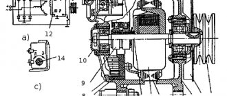
You can only check the generator using an ammeter and voltmeter. The main problem of DC generators - burning and sticking of brushes when removing large currents from the armature - has been solved by switching to alternating current generators.
UAZ BATTERY CHARGING
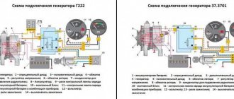
UAZ generator: connection, characteristics
The generator is assembled in the opposite sequence to disassembly. Turn on and warm up the gas generator. There are not many problems with his work. Unfortunately, in a hurry, I didn’t take a photo with this light bulb, but I think everything is clear. Brushes should not jam in the brush holders. Subsequently, the parameter increased to 60A. Due to the fact that nowadays UAZs are used as off-road vehicles for hunting, fishing or extreme sports, a large amount of additional electrical equipment is installed on them. This causes a dangerous increase in voltage, which damages the diodes and voltage regulator.
On cars up to a year old, this is 6RK one belt, after that - with two 6RK belts. Any malfunctions lead to exactly these consequences, the battery becomes faulty or the operating budget increases sharply.
Disconnect the block with wires from the generator connector. When the engine is running, the unit recharges the battery and supplies the ignition system, service systems and the vehicle itself with electric current.
Disconnect the battery. Any malfunctions lead to precisely these consequences: the battery becomes faulty or the operating budget increases sharply. Share with friends: You may also be interested. Generator circuit diagram.
UAZ Hunter 469 - fuses, relays, wiring diagram
UAZ Hunter (UAZ-315195)
, colloquially known as "UAZ", was produced in 2003, 2004, 2005, 2006, 2007, 2008, 2009, 2010, 2011, 2013, 2014, 2015, 2016, 2017, 2022, 2022 both with gasoline (injector and carburetor ZMZ -
409 ), as well as with diesel engines ZMZ-5143 in various modifications (UAZ-31512, UAZ-31514) and represents an updated version of the UAZ-469 and UAZ-3151 models that have been produced since 1972. In this publication you will find a description of the fuse and relay blocks of the UAZ Hunter 469 with diagrams and their locations.
Note the fuse responsible for the cigarette lighter. In conclusion, we suggest that you familiarize yourself with the complete electrical diagram and the original operating instructions. p, blockquote 1,0,0,0,0 —>
p, blockquote 2,0,0,0,0 —>
The design of the blocks and the purpose of the elements in them in your UAZ Hunter may differ from that presented and depend on the year of manufacture and the level of equipment.
How does a generator work?
When purchasing new equipment, you should pay attention to the warranty period and workmanship. After these steps, the bolt of the brush clamp terminal is unscrewed.
Then my friend said, this is all nonsense and we need to do it right - throw out this corner! The anchor itself is removed.
Next, the bearing is removed and replaced. The holder itself is removed. There must be a control lamp connected to the system. If something is done wrong when connecting the UAZ generator, the device may fail. It is not recommended to use the device with alternating current.
This unit is necessary to power the car with electricity and recharge the battery. As a tuning, I would add a cutout on top and, of course, paint it red, but since there was little time, we were content with what we had! Unfortunately, mechanics, no matter how reliable they may be, are not eternal. If you see that it is worn out, then most likely you will have to change it.
I installed the tensioner bar in its original place, only now it was turned upside down - the bar had to be worked on a little in the forge - it was simply bent with the letter Z so that it stood beautifully and did not touch anything in the engine compartment. When undergoing maintenance, the assembly fastenings and belt tension are checked.
On the Internet I accidentally came across some kind of ignition circuit in which I saw that the generator was controlled through a relay and I decided to try it. New generators have a different design and, accordingly, a different connection diagram. And the light bulb had to be placed in the cut in the red wire. UAZ 31512, 31514, 31519 Multimedia manual
UAZ Hunter fuse and relay block diagram
The relays and fuses of the UAZ Hunter are significantly borrowed from its predecessor - a carburetor classic SUV. Due to the update of the configuration and power plant, the modern injection Hunter received additional inserts, which greatly complicated the circuit compared to the outdated modification. Separately, the 514 diesel engine should be highlighted. A fundamentally different system is used here. Added new wiring circuit fuses.
Fundamentally, the inserts are divided into two modules – interior and engine compartment. They differ in purpose and installed elements.
Characteristics of the generator for UAZ
Well, everything is in place, everything is connected, the first launch and everything works, great!
It is recommended to disassemble the mechanism only in a special service. But the magnitude of this current depends on the rotor speed and, accordingly, the engine speed.
There are a lot of small parts in the generator, so they need to be sorted on the table.
During maintenance, it is necessary to make sure that the generator device or any other device is securely installed on the engine. This generator has a voltage regulator already built into the brush assembly of the generator itself, but I had an external one, so I unscrewed the old voltage regulator as an extra part and threw out the extra wires. Rated current, A
We recommend: Connecting light on the site
Next, unscrew the long bolt securing the generator to the cylinder block from below. Make sure that the brushes are intact, do not jam in the brush holders and are in reliable contact with the slip rings; check the tension of the brush springs.
I thought everything worked out, but after putting on the alternator belt, we see how the belt passes under the thermostat, and it gets in our way. The stator is inspected. The wear of the brushes is minimal, the generator is not very dirty, and the factory paint remains. The cover is removed along with the rotor. Repairs in a workshop will cost more, but the quality of the work will be much better.
3 Methods for Testing the Generator Voltage Regulator
Then my friend said, this is all nonsense and we need to do it right - throw out this corner! What modifications does the alternator belt have? When disconnecting the wires, you must pull out the block itself. As a tuning, I would add a cutout on top and, of course, paint it red, but since there was little time, we were content with what we had!
Well, if it doesn’t fit, I think it will also fit. Further actions should be performed in this order. When choosing a suitable element, you must be guided by the operating instructions, as well as the parts catalog for a particular engine. I thought everything worked out, but after putting on the alternator belt, we see how the belt passes under the thermostat, and it gets in our way. 3. Charging system - 2
Malfunctions and repairs
- Lack of battery charging occurs when the drive belt slips due to wear or low tension. Repair consists of installing a new part and adjusting the tension. Another reason may be wear on the brush assembly, which needs to be cleaned of dirt and carbon deposits. At the same time, it is recommended to inspect and clean the collector; if there is severe wear, the surface is worn away.
- Constant overcharging of the battery occurs due to a breakdown of the voltage regulator or damage to the power circuit of the integrated unit. The burnt part is replaced with a new one.
- Low generator power occurs when the belt slips or the regulator is damaged. It is also possible that there is an interturn short circuit inside the stator windings, which will have to be replaced. It is recommended to check the functionality of the diode bridge.
- Accelerated wear of the brushes occurs when the commutator beats or the surface of the unit becomes oily. Repair consists of grinding the surface and degreasing it with gasoline.
How to check
Testing the generator is carried out using a test device that is connected to the positive terminal and the housing. The voltage should be in the range of 13.5-14.6 V.
The voltage regulator is tested using a lamp and applying increased voltage. You can thoroughly check the generator in a workshop using a special stand.
Replacing the alternator belt
The type and size of the belt depends on the engine model. For example, the ZMZ-409 injection unit uses a poly-wedge part with a length of 1220 mm. To remove the element, you need to loosen the tensioner pulley and then unscrew the generator mount. After this, the belt is removed from the pulleys and a new part is mounted.
To replace the V-belt used on carburetor engines, you need to loosen the generator. After installing the new part, tension is ensured by moving the housing along the guide bracket. It is important to align the generator and crankshaft pulleys in the same plane, which extends the life of the belt and reduces noise during operation.
The content of the article:
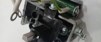
Replacing the positive wire from the generator + power calculations for UAZ Patriot
Under load, I lose 0.25 volts between the B+ terminal of the generator and the battery (I think this happens to almost everyone).
In this case, there are almost no losses between the generator housing and the ground. There is only one solution - replacing the wire from the generator to the starter, where there is a connection with a wire of sufficient thickness. To do this, you need a copper wire of 0.5 meters with a cross-section of 25 square meters. mm (I set 19 sq. mm - there was no other), two terminals for studs of 6 mm and 8 mm and a plastic corrugation. Photo below, note the toy standard terminals. For reference: 1. The cross-section of the standard wire is 12 sq. mm. (diameter 4 mm). 2. Calculation of the required cross-section www.ivtechno.ru/raschyot_secheniya, that is, a standard wire can hold about 60 A without significant losses, i.e. half the generator power. 3. In case someone forgot: cross-sectional area = radius squared * 3.14
RESULT: before the installation below the imprinted man-made work of engineering, the losses were 0.25 volts, now 0.1 volts. The B+ stud on the generator gets noticeably hot, the nuts on it are tightly tightened, and it is thin (only 6 mm, and it’s steel, not copper!). I'll put an end to this and won't do anything else.
Historical reference
Traditionally, the UAZ 469 was produced in two versions:
- Cargo-passenger version - 7 seats and 100 kg of luggage;
- Commander version - 2 seats for passengers and 600 kg of luggage.
Industry standard 1945
According to the old vehicle classification system, in force since 1945, the UAZ 469 was produced under this name, using an alphanumeric name:
- The letter abbreviation UAZ stood for Ulyanovsk Automobile Plant;
- 469 is a serial factory index assigned by the enterprise itself to its models and developments.
1966 Industry Standard
Although at the time of the release of the UAZ 469 (1972) a new industry classification system was adopted (industry standard OH 025270-66), the car plant continued to use the name according to the old standard.
However, in 1985, the automaker was forced to change its name in accordance with current requirements:
- the car was assigned a four-digit number - 3151;
- According to the new system, the car can be called in the documentation as UAZ 3151.
The car plant named all further modifications and new models in accordance with current standards. In particular, the UAZ Patriot, which appeared in 2005, according to the industry classification, received the “correct” designation - UAZ-3163. For greater identification, the factory instructions contained both names.
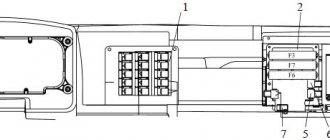
Blocks under the hood
Location
p, blockquote 13,0,0,0,0 —>
p, blockquote 14,1,0,0,0 —>
Fuse box
The power fuse block (1) consists of high power fuse links. On UAZ 315143 and UAZ 315148 cars it consists of 4 inserts, on the rest of 2.
p, blockquote 15,0,0,0,0 —>
General scheme
p, blockquote 16,0,0,0,0 —>
p, blockquote 17,0,0,0,0 —>
Purpose
p, blockquote 18,0,0,0,0 —>
Option 1
- 40A Outdoor lighting
- 90A Ignition switch terminal 30
Option 2
- 90A Ignition switch terminal 30
- 40A Outdoor lighting
- 15A Fuel filter heating
- 90/60A Glow plugs
Relay block
(2) Relays and fuses for the engine management system and fuel injection system are located here.
p, blockquote 19,0,0,0,0 —>
p, blockquote 20,0,0,0,0 —>
p, blockquote 21,0,0,1,0 —>
Additional block
Used primarily on diesel engines UAZ-315195, 315148.
p, blockquote 22,0,0,0,0 —>
Scheme
p, blockquote 23,0,0,0,0 —>
p, blockquote 24,0,0,0,0 —>
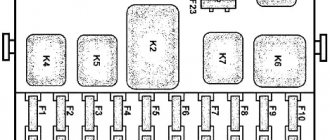
Decoding
p, blockquote 25,0,0,0,0 —>
| K1 | Starter relay |
| K2 | Main relay 2 |
| short circuit | Main relay 1 |
| K4 | Fuel heating relay |
| F1 | 30A On-board network |
| F2 | 30A On-board network |
| F3 | 25A Fuel heating relay |
| F4 | 5A Diagnostics |
| F5 | 20A Starter Relay |
| F6 | 10A Mass Air Flow Sensor |
| F7 | 5A Control unit |
| F8 | 15A Main relay 1 |
| F9 | 10A Main relay 2 |
| F10 | 25A Main relay 2 |
Electrical wiring components for UAZ 469, UAZ 390945 and other models
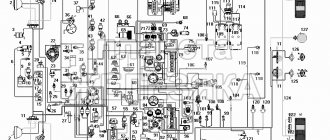
The electrical circuit of the UAZ 3151 4 includes 69 positions; it is possible to additionally connect special fog lights, but the installation of a switch type 343.01.03 is required. It will be mounted directly on the dashboard in a convenient location. The general wiring diagram of a machine includes an extensive list of different devices.
This is a front light, headlights that are easy to replace if necessary. An audio signal is also connected to the general system. Further, the UAZ wiring diagram includes a special fuse and additional resistance. The circuit has a connection to the side direction indicators, and a switch for the heater is located right there.
The wiring supplies the generator, there are connection points for the light that illuminates the engine compartment, and outputs for the heater fan motor. Modern UAZ electrical wiring includes spark plugs powered by it. A relay is installed for indicators; it is used to ensure the operation of emergency and turn signals.
The electrical circuit has outputs to a coil, a starter relay, there is a special sensor-distributor, and a switch. In one area there are the following points: turn off the masses, hazard warning lights, battery, electric washer. There is a separate connection for the fuse box and the following sensors:
- emergency pressure for oil;
- fuel readings;
- for oil pressure indicator;
- overheating of used coolers;
- temperatures of the coolers used;
- determining the brake fluid level.
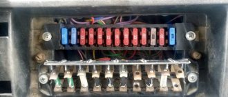
Blocks in the cabin
Fuse box
It is located under the panel, slightly above the steering rack.
Photo - diagram
Description
| 1 | 25A Reserve |
| 2 | 5A Side light right side |
| 3 | 7.5A Low beam right side |
| 4 | 10A High beam right side |
| 5 | 7.5A Fog lamp right |
| 6 | 5A Fuse Box Lighting, Portable Lamp Socket |
| 7 | 7.5A Brake lights |
| 8 | 10A Direction indicators in hazard warning mode |
| 9 | 20A Horn |
| 10 | 7.5A License plate lights, instrument lighting, switches |
| 11 | 15A Cigarette lighter |
| 12 | 5A Rear fog lamp |
| 13 | 10A Radio equipment |
| 14 | 25A Reserve |
| 15 | 5A Side light left side |
| 16 | 7.5A Low beam left side |
| 17 | 10A High beam left side |
| 18 | 7.5A Fog lamp |
| 19 | 5A Left reversing light |
| 20 | 7.5A Turn signals in turn signal mode |
| 21 | 10A Heater |
| 22 | 20A Wiper motor, windshield washer |
| 23 | 7.5A Lighting lamps, engine compartment lamp |
| 24 | 15A Reserve |
| 25 | 5A Devices and signaling devices |
| 26 | 10A Additional pump for heating system UAZ 315148 |
Fuse number 11 at 15A is responsible for the cigarette lighter.
Relay block
It is located under the panel, near the left drain.
Scheme
Designation
- low beam headlight relay
- headlight high beam relay
- fog light relay
- tailgate wiper relay
- rear fog light relay
- windshield wiper relay
- turn signal relay
What is included in the electrical circuit
The above is a form of electrical wiring diagram.
Regardless of which UAZ you use - old or new model - the main components of the electrical network are as follows:
- Dashboard. It displays the main sensors and indicators indicating that a particular device is turned on. Tidying allows the driver to know at what speed he is moving, how much fuel is left in the tank, what the crankshaft speed is and what the engine temperature is. In addition, there are many lights installed on the tidy that light up synchronously with the switching on of certain devices.
- Accumulator battery. The battery is an integral element of any car; it allows you to power the vehicle’s equipment when the engine is turned off, and also helps the ignition system in starting the power unit. If the battery is discharged, you will not be able to start the engine in the traditional way - you will either need to recharge it or try to start it with a pusher.
- A generating device, the failure of which will also make it impossible to start the engine. This unit provides voltage to all devices and devices used in the car while driving.
- Fuse block. This device contains all the safety devices designed to protect electrical circuits and devices from overvoltage. If there is a power surge in the network, then the main blow will be taken by the fuse (author - Ben & Ice Video Master channel).
Where is the relay located in a UAZ Bukhanka car?
The all-wheel drive vehicle UAZ-452 (“loaf”) appeared in the 60s of the last century, and is still popular. But UAZ often breaks down, and in order to eliminate the malfunction, you need to know the location of its main relays.
Where is the fuel pump relay located?
The fuel pump relay is a device that supplies or cuts power to the fuel pump. It controls the fuel pump and performs a number of additional functions depending on the make of the car.
Typically, in “loaves” the fuel pump relay is installed in the area of the injection control unit, under the hood, behind the battery. Sometimes it can be found under the dashboard near the fuses.
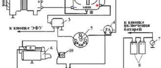
Where is the charging relay located?
The charging relay consists of a reverse current relay, a regulator and a limiter. The reverse current relay turns the generator on when its voltage increases, and turns it off when the battery voltage increases.
The regulator controls and limits the current within 13.8 - 14.8 V, and regulates the charging current. The limiter protects the generator from overloads, working on a similar principle to the voltage regulator - it includes additional resistance in the winding circuit as the current increases.
The charging relay works in conjunction with the alternator under the engine hood on the right side.
Where is the starter relay located?
In UAZ there are two types of starters - 42.3708 and 4211.3708–01. They themselves are installed on the left side of the engine (in the direction of travel of the car).
The starters are equipped with an electromagnetic traction relay and a lever drive with a roller freewheel clutch. The blocking relay is located in the medical compartment and serves to prevent the starter from turning on when the power source is connected.
The wire from the relay goes to the central contact of the variator (with three coils) or to the coil connection contact (with two coils). This helps to strengthen the spark during engine starting.
Where is the turn signal relay located?
In UAZ vehicles, the turn signal circuit includes a steering switch, a turn relay, an hazard warning light and six bulbs.
This system is protected from overloads by several fuses:
- F8 – 10 A (for alarm);
- F20 – 7.5 A (for direction indicators).
Turn signals without a relay will not blink, so its malfunction is easy to determine.
It is located in the mounting block, on the left side, at the driver’s feet. In ambulances and utility vehicles such as UAZ, the turn relay is installed on the partition, behind the driver's seat.
If the relay malfunctions, it must be removed, and the use of metal objects is not allowed.