Blocks in the cabin
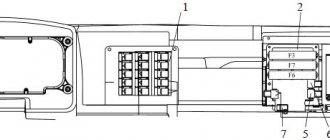
Fuse box
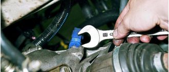
It is located in the center of the dashboard behind the protective cover and comes in two designs (flat and cylindrical fuses).
p, blockquote 3,0,0,0,0 —>
p, blockquote 4,0,0,0,0 —>
Option 1
Scheme
p, blockquote 5,0,0,0,0 —>
p, blockquote 6,0,1,0,0 —>
Description
p, blockquote 7,0,0,0,0 —>
p, blockquote 8,0,0,0,0 —>
| 1 | 16A Reserve |
| 2 | 8A Engine compartment light, cabin light |
| 3 | 8A Instrument lighting, switch lighting |
| 4 | 8A Rear fog lamp |
| 5 | 8A Right front and rear side lights, side light indicator |
| 6 | 8A Left front and rear side lights, side light indicator |
| 7 | 8A Low beam left headlight |
| 8 | 8A Low beam right headlight |
| 9 | 16A Main beam left headlight, high beam indicator |
| 10 | 16A High beam right headlight |
p, blockquote 9,0,0,0,0 —>
| 1 | 16A Reserve |
| 2 | 8A Hazard Alarm |
| 3 | 8A Direction indicators |
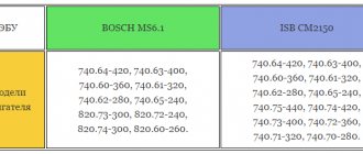
| 4 | 8A Reserve (GAZ-3309), MSUD control unit (GAZ-3307) |
| 5 | 8A Horn, portable lamp socket |
| 6 | 8A Brake signal |
| 7 | 8A Reserve |
| 8 | 8A Windshield wiper, washer |
| 9 | 16A Reversing light, wiper relay |
| 10 | 16A Heater, instruments, alarms |
Option 2
Scheme
p, blockquote 10,0,0,0,0 —>
p, blockquote 11,0,0,0,0 —>
Designation
p, blockquote 12,0,0,0,0 —>
p, blockquote 13,1,0,0,0 —>
| 1 | 25A Reserve |
| 2 | 15A Hazard Alarm |
| 3 | 15A Heater, brake air pressure drop buzzer |
| 4 | 10A Windshield wiper, washer |
| 5 | 10A Reserve |
| 6 | 10A Brake Signal Relay |
| 7 | 20A Horn, relay, portable lamp socket |
| 8 | 5A Tachograph (“+” battery) |
| 9 | 10A Wiper relay, reversing light |
| 10 | 10A Alarms, instruments, tachograph (“15”) |
| 11 | 5A Reserve |
| 12 | 15A Fuel Heater Relay |
| 13 | 15A Direction indicators |
p, blockquote 14,0,0,0,0 —>
| 1 | 25A Reserve or preheater |
| 2 | 15A High beam right headlight |
| 3 | 15A Main beam left headlight, high beam indicator |
| 4 | 10A Low beam right headlight |
| 5 | 10A Low beam left headlight |
| 6 | 10A Fog lights relay |
| 7 | 20A Reserve or preheater |
| 8 | 5A Engine control system unit (“50”) |
| 9 | 10A Engine compartment lamp, cabin and platform lamps, engine control system diagnostic blocks |
| 10 | 10A Illumination of devices and switches |
| 11 | 5A Engine control system unit (“15”) |
| 12 | 15A Side lights of the starboard side, headlight range control |
| 13 | 15A Left side parking lights, side light indicator, contour lights on the cab roof |
The following can be installed separately:
- A 20 amp heater control circuit fuse is installed in the heater control panel housing.
- The windshield wiper has an additional vibration-type thermobimetallic fuse.
Relay block
This block is located at the driver’s left foot, behind the plastic protection. Its execution and number of elements may vary.
p, blockquote 16,0,0,0,0 —>
General scheme
p, blockquote 17,0,0,0,0 —>
p, blockquote 18,0,0,0,0 —>
Decoding
- Ignition relay
- Starter Interlock Relay
- Pre-heater electrical equipment
- Reserve
- Horn relay
- Windshield wiper relay (separate, slightly to the right of the diagnostic connector)
Article: 89.3777
| Moscow, Khabarovskaya st. | 2 pcs. |
| Ekaterinburg | 2 pcs. |
| Nizhny Novgorod | 2 pcs. |
| Novosibirsk | 1 PC. |
| Permian | 3 pcs. |
| Lyubertsy, Mira st. | 27 pcs. |
| Mashkovo village, Lyubertsy district | 43 pcs. |
| Moscow, Ketcherskaya st. | 3 pcs. |
| Moscow, Varshavskoe sh. | 8 pcs. |
Data updated: 06/23/2021 at 19:57
- Parameters and characteristics
- Availability (91)
- Description
- Certificates (6)
- Product categories
Characteristics
| Order code | 667446 |
| Articles | |
| Catalog group | Electrical equipment, ..Electrical equipment |
| Width, m | 0.04 |
| Height, m | 0.04 |
| Length, m | 0.08 |
| Weight, kg | 0.033 |
Options
| Brand (TM) | AUTOTRADE |
| Delivery time upon order | 13 |
| Manufacturer | AUTOTRADE |
Shipping territory
Other partner warehouses and stores
+7 [email protected] Shipments only for legal entities by pre-order
Mon-Fri: from 9:00 to 18:00, Sat, Sun: closed
+7 [email protected] Mon-Fri: from 9:00 to 20:00, Sat: from 9:00 to 18:00, Sun: from 9:00 to 16:00
+7 [email protected] OPT: Mon-Fri: from 9:00 to 18:00, Sat-Sun: closed. Retail: Mon-Fri: from 8:30 to 17:30, Sat: from 10:00 to 16:00, Sun: closed
+7 [email protected] Mon: from 8:30 to 18:00, Tue-Thu: from 9:00 to 18:00, Fri: from 9:00 to 17:30, Sat-Sun: closed
Blocks under the hood
Fuse box
Spare fuses are located in the fuse box cover.
Option 1
A fuse block of four fuses for 60A, 30A, 60A and 30A is installed on the power steering reservoir mounting bracket.
p, blockquote 21,0,0,0,0 —>
The 60A extreme fuse protects the glow plug pin circuit. A 30A fuse protects the vehicle's light circuit. The second 60A fuse protects all vehicle circuits except the starter circuit. A 30A extreme fuse protects the engine control unit circuit.
p, blockquote 22,0,0,0,0 —>
Option 2
On the right side of the hood side panel there is a fuse block of four fuses for 30A, 40A, 90A and 125A.
p, blockquote 23,0,0,0,0 —>
A 30A fuse protects the engine control unit circuit. A 40A fuse protects the vehicle's light circuit. A 90A fuse protects the vehicle's common positive circuit. A 125A fuse protects the air heater circuit.
p, blockquote 24,0,0,0,0 —>
Relay block
It is mounted on a special reader and here the engine control relay and spark plugs can be located.
p, blockquote 25,0,0,0,0 —>
p, blockquote 26,0,0,0,0 —> p, blockquote 27,0,0,0,1 —>
That's all. And if you want to help supplement the material, then write in the comments.
Yes, you can install the G 273V1 Kamazovsky, but you need to adapt the pulley.
A pulley from the Valdai generator will fit on it
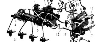
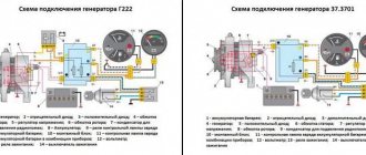
Generator 5101.3701 is made according to a circuit with additional diodes. Voltage regulator Ya120M12. Old-style figure-eight diode bridge BPV 56-65-02 with two wires.
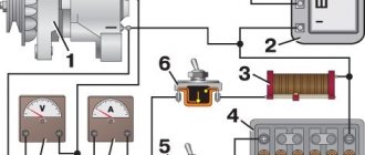
The generator consists of a housing, stator winding, rotor, diode bridge and built-in voltage regulator.
The housing and main parts are similar to the KZATE 372.3701 generator for eight, however:
The stator winding is designed for 28 Volts and will not work from a figure-eight generator.
The generator rotor is designed for 28 Volts and will not work with a figure-eight generator.
The peculiarity of this type of generator is that a cap is made at the rear of the generator, in which a voltage regulator is mounted. This design improves the splash protection required for SUVs. When repairing such generators, it becomes difficult to arrange the wires connecting the voltage regulator and the generator. How to arrange the wires correctly?
Operating principle of the generator
Purpose of the voltage regulator. 28 Volt voltage regulator YA120M12 and its analogues
Service
If you provide the starter with preventive maintenance, its life may increase.
It won’t hurt to adhere to certain rules during repairs. Will be useful:
- Periodically check the degree of tightening of the starter mounting nuts, at least once every 10 thousand km of the vehicle.
- If oil gets on the device, wipe the starter with a rag containing a degreaser.
- If it is heavily oiled, remove and disassemble the starter, removing all traces of oil on the internal parts. At the same time, it is worth checking the condition of the brushes - if the graphite height is less than 6 mm, then they should be replaced.
- When assembling the starter, it is necessary to lubricate the solenoid relay core with liquid oil (motor or spindle). This will prevent the core from sticking in the retractor cylinder.
Generator circuit 5101.3701
Initial generator excitation
When starting, the initial excitation comes from the battery. Then, when the generator starts working, it itself transfers part of its current to excitation.
The light bulb, with its resistance, limits the initial excitation current to 100 mA. This current is sufficient to excite the generator. The light is on, indicating that the excitation circuit is intact, the excitation current is flowing and the generator is ready for operation.
Excitation of generator 5101 through an additional rectifier
This generator uses a circuit with additional diodes to power the excitation winding. An additional rectifier consisting of three small diodes is provided in the diode bridge of the generator. For these generators, a diode bridge of the figure-eight generator 372.3701 is used, a brand of diode bridge BPV 56-65-02 of the old type with two wires.
Figure-of-eight diode bridge
The generator circuit with additional diodes allows you to receive the excitation current not from the output of the generator, but from the output of additional diodes. This point is not connected to the battery positive and therefore accidental discharge of the battery through the generator excitation winding is excluded. The excitation current in such a circuit flows only inside the generator and does not use external circuits and the ignition switch (except for the initial excitation). The reliability of such a scheme is much higher than schemes without additional ones. diodes.
When the generator is running, the excitation current no longer comes from the battery, but from the generator through an additional rectifier. The magnitude of this current is determined by the resistance of the field winding and is (3-5 A, rotor winding resistance is approximately 6 Ohms), such a current is necessary to obtain the full power of the generator. The output from the additional rectifier via the red wire provides power to the voltage regulator circuit.
The light on the instrument panel is a convenient indicator that allows you to monitor the operation of the generator.
The light is on, which means the generator is not working.
Thus, if after starting the engine the light goes out, then everything is fine - the generator is working.
Generator assembly 5101.3701. How to arrange the wires correctly?
how to connect the generator wires on a GAZ 3309
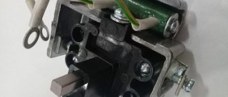
The generator brush assembly is similar to the generator brush assembly from the Zhiguli G221, but it has three connection points and both brushes are isolated from ground, so do not forget to put an insulating washer under the brush assembly mounting screw.
A simpler connection procedure is also possible without disrupting the circuit.
Technical data
Starter ST-230 has the following characteristics:
- Rated power of the device is 1500 W;
- Rotation – right;
- Current consumption in no-load mode – up to 85 Amperes;
- Current consumption at full load – up to 530 Amperes;
- Poles in the excitation winding – 4;
- Number of Bendix gear teeth – 9;
- Torque – does not exceed 2.25 kgf/m;
- Rotation speed – 40 rpm.
Return to contents
What could happen to the generator 5101.3701 on the GAZ 3309
If, when you turn on the ignition, the battery discharge light on the instrument panel does not light up, then the generator will not work after starting the engine; look at the voltmeter; the arrow will remain to the left.
If the engine starts and the light does not go out, it means the generator has not started (check the belt)
If the light comes on while driving, it means the generator has stopped working.
If the light blinks, it means it's time to replace the brushes.
If the light is dimly illuminated, the generator is faulty. Change the diode bridge
If the light bulbs glow too brightly, flicker, and the battery becomes wet, then the voltage is too high and you need to urgently replace the voltage regulator.
If the light goes out only at high speeds, then the generator is faulty
If the generator makes loud noise, the bearings need to be replaced. If the generator is very old, then it is better to replace the entire generator.
In case of any malfunction, you need to go to where the generator will be repaired, otherwise in two hours you can be hopelessly stuck
This story began after the winter of 2022. In winter, I had a desire to go through the wiring
obviously not understanding auto electrics.
I decided to start with the instrument panel, unscrewing and recording the location, everything that was visible was turned off, after sitting and thinking, I isolated everything that was in doubt and put everything back together
.
I was somehow afraid of causing unnecessary trouble, although the wiring issue is not closed to this day
. Some photos of my terrible wiring
Well, okay, spring days have arrived and it’s time to wake up the diesel engine. After recharging the battery, they fell into place
.
There were no problems with starting, it started quite well, although the fast start may have contributed to this. And what didn’t I see? Correctly positive ammeter readings
. Where could they have gone? Probably messed up with the wiring, double-checked everything as it was before. I started reading forums and asking experienced people, there were a lot of assumptions about the voltage regulator called a chocolate bar in common parlance, I had a Y120M1.
The replacement did not give any result. The brushes were worn out by life, but new brushes did not solve the problem. I called a friend who understands more about electrics than I do. The verdict is that the belt is tensioned, does not slip, the brushes reach the slip rings, when dialing the values of the old and new voltage regulators, the readings are the same, the rotor on the housing is not broken, the slip rings ring with each other
The stator on the housing is not pierced, the contacts that come out of it ring with each other, they call it a little, by insulating with plastic the places where it looks like there could be a breakdown
The diode bridge operates in one direction; the spread of values on the diodes is minimal.
As if everything should be arbeiten.
However, there is still no charge. When the ground is turned on on the positive side of the generator, the voltage from the battery, whether with the car running or when the car is turned off, does not change, only with the gradual removal of the battery it changes
, when the mass is turned off, nothing comes out of the generator.
(You can also check with a light bulb; it should light when the generator is excited and the ground is disconnected). The ammeter needle does not change its position when you press the gas. Only red to the main positive terminal and yellow to the relay regulator are suitable for the generator, in principle, everything worked in this composition
.
They gave the generator kzate with 4301 to work before the car accident, after that they did not start it
, did not disassemble it without external damage, but the body was not broken.
the symptoms are the same when starting the car nothing happens. Maybe he wasn't a worker. It’s more expensive for you to disassemble and assemble other people’s things, I tried no, no. So I left for the season to recharge (I didn’t work in the car, I went out for my own needs)
With the thought that buying a new one was expensive and they didn’t work,
I took another one in the spring of 2022 from a car that went into cutting
for it, they also didn’t say with certainty that it was working, Maza was started from a pusher. The person to whom the car was driven and who subsequently gave me the generator was absent at that moment. When he arrived, his result was also zero. I didn’t know what to do anymore, there were 3 generators and not one of them was working, I’d buy a new one and it would be the same story, if mine were dying somehow gradually, then there was doubt... But I had to drive around, recharging the car one battery at a time, I was pretty tired. I ordered a generator the same as the one G273V had.
Under the hood of a GAZ-3309 car with an MMZ D-245.7 Euro-3 engine, a fuse block of four fuses for 60A, 30A, 60A and 30A is installed on the power steering reservoir mounting bracket.
Description
The electrical circuit of the GAZ-3307 is a drawing on which there are pictograms of the electrical elements of the car, connected to each other by switching lines indicating wires. The equipment is located approximately where it is when looking at the machine from above, although deviations (sometimes significant) are possible. On the left are usually the headlights and sidelights of the front of the car, to the right are the electrical equipment of the engine compartment, interior and rear lights.
Electrical circuits are available in black and white and color. The latter are easier to read; the colors of the lines are the same as those of the corresponding wires. Often electrical components are shown in the form of pictures (instrument panel, starter, headlights, etc.), they can be recognized without looking at the “legend” (the explanatory text under the diagram or on the side of it). An example of a color wiring diagram is shown below.
Black and white diagrams are usually more detailed and often provide additional information (for example, thin lines show current conductors inside devices). The color of the wires is indicated by a letter (H - black, Z - green, and so on). The numbers (2; 0.5 and others) in the breaks in the switching lines indicate the cross-sectional area of the wire in square millimeters. There are standard pictograms and conventional images of certain devices. Next to them (sometimes on a callout) is a number or letter with numbers. This is the designation of the element whose name is indicated in the “legend”.
Troubleshooting
If any device fails, using an electrical circuit it is easy to check whether it has failed or whether the electrical circuit has been interrupted somewhere.
Power supply circuit for a GZ-3307 car. To do this, you will need a test light with wires and clamps or a tester turned on in voltmeter mode (voltage detection). We connect one clamp of the light bulb (tester) to the input contact of the element being tested, the other to the “ground”, that is, the negative terminal of the battery or any part of the frame, body or engine (cleaned of paint).
Measures to prevent premature starter failure
The process of pressing the bearing out of the starter
- Do not turn the ignition key clockwise while the engine is running;
- If the engine does not start within five seconds, you need to release the ignition key. A second attempt to start should be made no earlier than after ten seconds;
- It is forbidden to start the engine at speed by cranking the starter. An increased load on the trigger mechanism will quickly lead to failure of the device;
- In frosty weather, it is recommended to use a preheater; engine oil should be filled according to the season;
- If the engine starts, the ignition key should be released - the bendix should disengage from the flywheel.
GAZ 3309 starter: where is it located, how to remove, replacement
GAZ 3309 is a popular truck that was produced in the USSR; later, another modification of the vehicle began to be produced in Russia; its main difference was that the gasoline engine was replaced with a diesel engine, which is labeled as MMZ D-245.7E4.
It has several modifications, the most popular version is an engine that produces 125 “horses” and complies with the Euro-4 environmental class. It is worth noting that there is another diesel engine, but it is less common.
The car is still in production, despite all its modern competitors, and the GAZ 3309 is still a frequent participant in road traffic in our country. The whole secret is the simplicity of the device and the reliability of spare parts. Of course, any mechanism has its own resource, and the GAZ 3309 also has breakdowns. Let's touch on the issue of the starter of this car in more detail.
Types of faults
Sometimes people mistakenly blame the starter, but in the end it turns out that it is not the fault. The thing is that the starter works in conjunction with other systems and components of the car (starting-charging circuit).
In general, all starter failures can be divided into two large groups:
- Mechanical faults,
- Electrical breakdowns.
Each group has its own nuances, so it is worth considering them in detail.
Electrical breakdowns
If the starter does not turn the engine at all or does so very slowly (with insufficient power to start the engine), you must first check the electrical circuit. This must be done from the battery to the starter.
The rechargeable battery (AB) should be given special attention in this matter. Need to check:
- Charge (the battery must be fully charged),
- Ground contacts (they must be reliable and well secured),
- Wire from the solenoid relay terminal (integrity and good contact),
- Wire from the battery to the starter (integrity and good contact),
- Contact group of the ignition switch (serviceability).
The above-mentioned problems occur when it is possible to turn the key in the ignition switch, but there is no activation of the retractor relay (the armature does not rotate) or there is a break in the winding of the traction relay, as well as a short circuit of the turns or to ground. In addition, slow turning of the flywheel may indicate problems with the electrical part of the starter.
If there are no visible visual faults with the starter, then you need to dismantle it in order to examine it more carefully. Thus, it is possible to determine whether the commutator is burning or to find a short circuit in its plate.
But the experience of studying the issue suggests that the most common electrical malfunction is wear or hanging of the brushes.
Now we can distinguish three main breakdowns from this category of faults:
- Poor contact between the brushes and the commutator,
- Broken traction relay,
- Armature commutator wear.
Mechanical problems
If the starter works, but the engine does not start, then the problem is from this category. In this case, you need to check the following details:
- Overrunning clutch lever,
- Clutch ring,
- buffer spring,
- Flywheel crown.
When the starter is running, the car engine does not start for the following reasons:
- Clutch slipping (failure of the release lever, its jumping off the axis, wear of the clutch drive ring or wear of the buffer spring). Defective parts should be replaced.
- If a grinding noise is heard during startup, this is wear on the flywheel ring teeth. The gear travel should be checked for any blockages, and the condition of the buffer spring should be checked for functionality.
- If a very strange noise is heard, then you should check from the “pit” and engine compartment for such faults as wear of the bearing sleeve, journals on the armature shaft, loosening of the starter mounting bolts and damage to the teeth. In addition, the pole inside the starter may become loose.
Device
A starter model ST-230 is installed on the GAZ 53 truck; it is screwed with two nuts on the clutch housing on the left side of the internal combustion engine in the direction of travel (closer to the driver). The circuit is very simple, fundamentally it is no different from the circuit of a similar device on another model of car or truck.
Detailed diagram of the starter device for GAZ 53
- Frame. It is metal, cylindrical in shape;
- Stator winding. Installed inside the housing and placed along its walls;
- Armature (rotor). It is a moving part in the trigger mechanism. The armature shaft rotates in 3 bearings (one in the front cover, two on the intermediate support);
- Brush unit. 4 brushes contact the rotor commutator, causing it to move;
- Front cover. It closes the brush assembly, protecting it from dirt, water and oil;
- Bendix. Gear device, the gear meshes with the engine flywheel and drives the engine;
- Rear cover (Bendix housing). It is a protective casing for the Bendix; the rear end of the housing serves as a support for the entire axis of the rotating shaft;
Appearance of the starter for the GAZ 53 truck
The connection diagram is simple, the mechanism is simple, the connection is made through a solenoid relay. One contact of the relay is supplied with a constant voltage of 12 Volts, the other contact is supplied with power from the ignition switch.
When the key is turned, under the influence of an electromagnetic field, the core in the relay moves and activates the bendix.
Almost simultaneously, the core closes the contacts on the relay, turning the electrical circuit into operation. The starter turns, starting the engine. It is important to release the ignition key in time to avoid damage to the starting mechanism.
Malfunctions of the ignition system of GAZ-3307
For example, let's find a fault in the ignition system, which is one of the most important in a car. Failure or poor performance of any of the elements is a serious problem, especially while traveling. The engine stalls or runs intermittently, it is advisable to quickly find and eliminate the cause.
First, make sure that the problem is in the ignition system (there may also be a fuel supply malfunction). Remove the wire from any spark plug and bring its end to ground at a distance of 6–9 mm. When the engine is cranked by the starter, a spark should appear. Be careful, the circuit is under high voltage; you should work with rubber gloves or use improvised objects that do not conduct current, for example, wooden ones, holding the wire with their help. If there is no spark, remove the central wire from the distributor cover and check it in the same way as a spark plug.
There is a spark - the problem is in the breaker-distributor (item 3), if not - let's continue the search. Make sure that current is supplied to the induction coil terminal (item 5). To do this, connect the clamps of the control light to the corresponding connector and ground: the light should light up (with the ignition on). Similarly, check the output of the switch (item 4) with the + sign. If there is current, connect a light bulb (with a power of no more than 3 W) to the short-circuit terminal and ground. It should flash when the starter is turned on. If this happens, the ignition coil is faulty.
If the light is on continuously or does not light up, the switch is faulty (unfortunately, a typical problem on the GAZ-3307).
If current is not supplied to the coil, we determine according to the diagram the next element in the circuit - the ignition switch (item 9). Both contacts must be energized (with the ignition on); if only the incoming one is energized, then the lock is faulty.
The next element in the circuit is the fuse (item 7). It must be checked if there is no voltage at the incoming terminal of the ignition switch. If a fuse is blown, try to find the cause before replacing it. Most likely, this is a short circuit; its sign is a dark spot at the breakdown site. The wire must be cleaned, the burnt ends connected (if necessary) and carefully insulated.
Price order
If the starter is faulty, it can be replaced or repaired. There are no problems with the parts, and you can also look for used parts. True, when buying a used part there is a certain amount of risk - the performance of the starter is determined only by the assurances of the seller.
A new Belarusian-made starter (BATE) costs approximately 6000-7000 rubles, the solenoid relay for it is sold for 1000-1200 rubles.
The price for Borisov-made Bendix ranges from 350-550 rubles and depends on the region of sale and the seller. Of course, the price will be cheaper in large wholesale companies. Due to changes in the ruble exchange rate, the cost of gas 53 dump truck parts may increase; recently they have already become higher. You can buy a used starter from advertisements on Avito for around 1500-2500 rubles.