Relay valve
Fast braking/release of pneumatic units, as well as reducing the delay and response time of the components of the pneumatic braking system. The appearance and structure are shown in Figures 250 and 251.
Figure 250. Appearance, structure and symbol
When the brake system is applied, compressed air passes through port 4 into chamber A and presses the piston (a) down. The outlet (c) is closed and the inlet (b) is opened. Compressed air supplied to terminal 1 passes into chamber B and through terminals 2 enters the brake chambers connected further.
Compressed air passes into chamber B and loads the lower surface of the piston (a). As soon as this pressure exceeds the control pressure in chamber A, piston (a) rises. The inlet (b) closes and the equilibrium position has been reached.
In the event of a partial drop in control pressure, the piston (a) rises again, the outlet (c) opens and excess compressed air at port 2 is released into the atmosphere through pressure relief channel 3. In the event of a complete drop in control pressure at port 4, the compressed the air in chamber B moves the piston (a) to its uppermost position, the outlet (c) opens. The further connected brake chambers are completely released via pressure relief channel 3.
Installation recommendations.
To secure the relay valve, optionally two or four M8 valve body connecting bolts are used. The valve is mounted so that the bleed channel 3 faces down.
Source
Kamaz brake accelerator valve
The accelerator valve supplies compressed air to the energy accumulators and is designed to reduce the response time of the parking and emergency brake drive by reducing the length of the compressed air inlet line into the spring energy accumulators and releasing it from them into the atmosphere
It consists of a control chamber 2, a piston 3, an exhaust valve 1 and an intake valve 4, and an intake valve spring 5. Compressed air from the receiver is constantly supplied to terminal III
Pin IV is connected to the manual brake valve, pin I is connected to the cavities of the spring energy accumulator cylinders, pin II is connected to the atmosphere.
In the initial position, when the car is released (Fig. b), piston 3 is in the lower position, under the influence of compressed air, the exhaust valve 1 is closed, the inlet valve 4 is open, since the area of the upper part of the piston 3 is larger than the area of the lower one, and the pressure in cavity A and chamber 2 are the same.
Terminal I is disconnected from atmospheric terminal II , and the pistons of spring energy accumulators are under compressed air pressure and do not act on the brake chamber rods.
When braking (Fig. 1c), compressed air from chamber 2 is released into the atmosphere through the atmospheric outlet of the manual brake valve.
With a drop in pressure in chamber 2, piston 3 moves upward, inlet valve 4 closes under the action of spring 5, and outlet valve 1 opens.
Through outlet I and the open outlet valve 1, the cavities of the spring energy accumulators communicate with the atmospheric outlet II .
The pressure in the cavities of the cylinders of spring energy accumulators decreases, the springs are unclenched, and the brake mechanisms are braked.
Release of the brake is carried out by supplying compressed air from the tap to terminal IV and then into chamber 2.
Piston 3, moving downward, first opens exhaust valve 1, then inlet valve 4.
Compressed air comes from the receiver into the cavities of spring energy accumulators.
The pressure in the cavities of the cylinders of spring energy accumulators increases, the springs are compressed, and the brake mechanisms are released.
The proportionality between the control pressure in terminal IV and the pressure in the cavities of the spring energy accumulators (in terminal I ) is maintained by piston 3.
When terminal I a certain pressure, piston 3 moves upward to the closed inlet valve 4, moving under the action of spring 5, and further pressure growth stops.
When the pressure in port IV , piston 3, under the influence of higher pressure in port I , moves upward and breaks away from outlet valve 1.
Compressed air from the cavities of spring energy accumulators escapes into the atmosphere through open valve 1 and atmospheric outlet II , the pressure in cavity A decreases.
Kamaz brake adjustment lever, ratchet
_______________________________________________________________________________
Brake system and brake drive of Kamaz vehicles
Brake system of Kamaz vehicles
The braking system of Kamaz-5320 vehicles consists of four autonomous braking systems: service, spare, parking and auxiliary.
Although Kamaz brake systems have common elements, they operate independently and provide high braking efficiency in any operating conditions.
In addition, the Kamaz vehicle is equipped with an emergency brake release drive, which makes it possible to resume the movement of the vehicle (road train) when it is automatically braked due to a compressed air leak, an alarm and control devices that allow monitoring the operation of the pneumatic drive.
The Kamaz-5320 braking system is designed to reduce the speed of the vehicle or stop it completely.
The brakes of the Kamaz-5320 service brake system are installed on all six wheels of the vehicle. The drive of the working brake system of KamAZ-5320 is a pneumatic dual-circuit one; it operates separately the brake mechanisms of the front axle and the rear bogie of the vehicle.
The drive is controlled by a foot pedal, mechanically connected to the brake valve. The executive bodies of the drive of the working brake system of KamAZ-5320 are the brake chambers.
The Kamaz-5320 spare brake system is designed to smoothly reduce the speed or stop a moving vehicle in the event of a complete or partial failure of the working system.
The Kamaz parking brake system provides braking for a stationary vehicle on a horizontal section, as well as on a slope and in the absence of a driver.
The parking brake system on Kamaz vehicles is designed as a single unit with the spare one, and to activate it, the hand valve handle should be set to the extreme (upper) fixed position.
Thus, the Kamaz brakes of the rear bogie are common to the working, spare and parking brake systems, and the latter two also have a common pneumatic drive.
The Kamaz brake auxiliary system serves to reduce the load and temperature of the brake mechanisms of the service brake system.
The auxiliary braking system on Kamaz vehicles is an engine retarder, when activated, the engine exhaust pipes are blocked and the fuel supply is turned off.
The Kamaz emergency brake release system is designed to release spring energy accumulators when they are automatically activated and the vehicle stops due to a compressed air leak in the drive.
The drive of the Kamaz emergency brake release system is duplicated: in addition to the pneumatic drive, there are emergency brake release screws in each of the four spring energy accumulators, which allows the latter to be released mechanically.
The Kamaz alarm and control system consists of two parts:
— Light and acoustic signaling about the operation of brake systems and their drives. At various points of the Kamaz pneumatic drive there are built-in pneumatic-electric sensors, which, when any braking system, except for the auxiliary one, closes the circuits of the electric brake light lamps.
Pressure drop sensors are installed in the drive receivers and, if there is insufficient pressure in the latter, they close the circuits of the signal lamps located on the vehicle's instrument panel, as well as the sound signal (buzzer) circuit.
— Valves of control terminals, with the help of which the technical condition of the Kamaz pneumatic brake drive is diagnosed, as well as (if necessary) the selection of compressed air.
Tractor vehicles are also equipped with a set of pneumatic devices for actuating the brake mechanisms of a Kamaz trailer (semi-trailer) with a single-wire and double-wire drive.
The presence of such a drive on tractors ensures their aggregation with any trailers (semi-trailers) that have a pneumatic drive of the brake mechanisms.
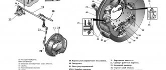
Kamaz brakes (Fig. 1) are installed on all six wheels, the main unit of the brake mechanism is mounted on caliper 2, rigidly connected to the axle flange.
Fig.1. Kamaz car brake
1 — block axis; 2 — caliper; 3 — shield; 4 - axle nut; 5 — pad axle lining; 6 — block axis pin; 7 — brake pad; 8 - spring; 9 — friction lining; 10-bracket for expanding fist; 11 — roller axis; 12 — expansion fist; 13 - roller; 14 — adjustment lever
Two brake pads 7 with friction linings 9 attached to them, made along a crescent-shaped profile in accordance with the nature of their wear, rest freely on the eccentrics of the axles 1, fixed in the caliper.
The axes of the shoes with eccentric supporting surfaces allow the shoes to be correctly centered relative to the brake drum when assembling the brake mechanisms.
The Kamaz-5320 brake drum is attached to the wheel hub with five bolts.
When braking, the KamAZ-5320 pads are moved apart by an S-shaped fist 12 and pressed against the inner surface of the drum. Between the expanding fist 12 and the pads 7, rollers 13 are installed, which reduce friction and improve braking efficiency.
The pads are returned to the released state by four release springs 8. The expansion fist 12 rotates in the bracket 10, bolted to the caliper.
The brake chamber is installed on this bracket. At the end of the expanding fist shaft there is an adjusting lever 14 of the worm type, connected to the Kamaz-5320 brake chamber rod using a fork and a pin. A shield bolted to the caliper protects the brake mechanism from dirt.
The Kamaz adjusting brake lever (ratchet) is designed to reduce the gap between the pads and the brake drum, which increases due to wear of the friction linings.
The device of the adjusting lever (ratchet) KamAZ is shown in Fig. 2. The adjusting lever has a steel body 6 with a bushing 7.
Fig.2. Adjusting brake lever (ratchet) Kamaz
1- cover; 2 - rivet; 3 - gear wheel; 4 - plug; 5 - worm; 6 — body; 7 - bushing; 8- locking bolt; 9 — clamp spring; 10 — retainer ball; 11 - worm axis; 12 - oiler
In the body of the Kamaz ratchet there is a worm gear 3 with splined holes for installation on the expansion fist and a worm 5 with an axle 11 pressed into it.
To fix the worm axis there is a locking device, the ball 10 of which enters the holes on the worm axis 11 under the action of a spring 9 resting against the lock bolt 8.
The gear wheel is kept from falling out by covers 1 attached to the lever body 6. When the axle is turned (by the square end), the worm turns wheel 3, and the expansion fist turns with it, pushing the pads apart and reducing the gap between the pads and the brake drum.
When braking, the adjusting brake lever (ratchet) of the Kamaz vehicle is turned by the brake chamber rod. Before adjusting the gap, lock bolt 8 must be loosened one or two turns; after adjustment, tighten the bolt securely.
Adjusting Kamaz brakes
Kamaz brakes have two adjustments - partial and full. Partial adjustment of Kamaz brakes is carried out during operation and is aimed at restoring the normal gap between the shoe linings and the brake drum.
The need to adjust the Kamaz brakes is judged by the output of the brake chamber rods, which should be 20mm when you press the brake pedal.
The required stroke value is set using a worm pair of the adjusting lever. When adjusting, the brake of the Kamaz vehicle should be cold, the parking brake should be released, the locking bolt 8 should be loosened by one or two turns and securely tightened again.
To obtain equal braking efficiency for the right and left wheels, the output of the rods of the right and left brake chambers on each axle must be the same.
Full adjustment of Kamaz brakes is carried out after disassembling them (replacing linings or pads). The purpose of this adjustment is to position the shoes correctly relative to the drum.
Kamaz brakes are adjusted using the eccentric axles of the pads and the adjusting lever.
The brake is considered to be adjusted correctly if the gap between the lining and the brake drum, measured with a feeler gauge through the hatch in the support disk at a distance of 30 mm from the edge of the lining in the upper and lower parts, is within 0.2 ... 0.4 mm, and the feeler gauge is 0.1 mm thick mm does not extend along the entire width of the block.
Kamaz brake drive
Schematic diagrams of the Kamaz brake drive are shown in Fig. 3. The source of compressed air in the drive is compressor 9.
The compressor, pressure regulator 11, fuse 12 against freezing of condensate, condensation receiver 20 make up the supply part of the drive, from which purified compressed air at a given pressure is supplied in the required quantity to the remaining parts of the pneumatic brake drive and to other consumers of compressed air.
The Kamaz-5320 pneumatic brake drive is divided into autonomous circuits, separated from each other by safety valves. Each circuit operates independently of other circuits, including when faults occur.
The Kamaz pneumatic brake drive consists of five circuits, separated by one double and one triple safety valve.
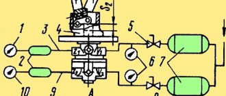
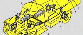
Rice. 3. Diagram of the pneumatic drive of the brake mechanisms of the Kamaz 5320 car
A - control output of circuit IV; B, E - valves of control terminals of the third circuit; C - control output of circuit I; D - control output of circuit II; N — brake control line of a two-wire drive; P — connecting line of a single-wire drive; K - line supplying a two-wire drive; 1 — brake chambers type 24; 2 — parking brake system control valve; 3 — emergency brake release valve for the parking brake system; 4 — auxiliary brake system control valve; 5 — two-pointer pressure gauge; 6 — control lamps and sound signaling device; 7 — control valve; 8 — pressure limitation valve; 9 - compressor; 10 — pneumatic cylinder for driving the engine stop lever; 11 — pressure regulator; 12 - anti-freeze fuse; 13 — double safety valve; 14 — sensor for turning on the solenoid valve of the trailer brake mechanism; 15 — rechargeable batteries; 16 — two-section brake valve; 17 — triple safety valve; 18 — pressure drop sensor in the receiver; 19 — condensate drain valves; 20 — condensing receiver; 21 — air bleed valve; 22 — receivers of circuit II; 23 — pneumatic cylinder for the auxiliary brake system flap drive; 24, 25 — receivers of circuits I and III; 26 — brake chambers of type 20×20; 27 — sensor for turning on the warning lamp of the parking brake system; 28 — energy accumulators; 29 — accelerator valve; 30 — automatic brake force regulator; 31 — trailer brake control valve with a two-wire drive; 32 — two-line valve; 33 — sensor for turning on the brake signal; 34 — trailer brake control valve with a single-wire drive; 35 — single safety valve; 36 — rear lights; 37 — isolation valves; 38, 39 — connection heads type A and type “Palm”
Fig.4. Diagram of pneumatic brake drive for Kamaz-65115 vehicles
1 - water separator; 2 - compressor; 3 - cooler; 4 - four-circuit safety valve; 5 - automatic brake force regulator; 6 — pressure regulator; 7 - brake signal switch; 8 - brake valve; 9 — pneumatic cylinders for the flap drive of the auxiliary brake system mechanism; 10 — parking brake system control valve; 11 - proportional valve; 12 - pneumatic cylinder for driving the engine stop lever; 13 — auxiliary brake system control valve; 14 - pressure gauge; 15- brake chambers type 30/30; 16 - receiver circuit 1Y; 17 — receivers of circuit 11; 18 — condensate drain valve; 19 — brake chambers type 20/20; 20.24 - accelerator valves; 21 - two-line bypass valve; 26 switch for the parking brake system warning lamp; 23 — receiver of circuit III; 25 — receiver of circuit I; 26 — switch for warning lamp for air pressure drop in circuit III; 27 — emergency brake release valve
Circuit I of the service brake drive of the Kamaz front axle consists of part of a triple safety valve 17; receiver 24 with a capacity of 20 liters with a condensate drain valve and pressure drop sensor 18 in the receiver, part of a two-pointer pressure gauge 5; lower section of a two-section brake valve 16; valve 7 control terminal (C); pressure limit valve 8; two brake chambers 1; brake mechanisms of the front axle of the tractor; pipelines and hoses between these devices.
In addition, the drive circuit for the service brakes of the Kamaz front axle includes a pipeline from the lower section of the brake valve 16 to valve 31 for controlling the brake systems of a trailer with a two-wire drive.
Circuit II of the service brake drive of the rear Kamaz truck consists of a part of the triple safety valve 17; 22 receivers with a total capacity of 40 liters with condensate drain valves 19 and pressure drop sensor 18 in the receiver; parts of a two-pointer pressure gauge 5; the upper section of the two-section brake valve 16; control output valve (D) of the automatic brake force regulator 30 with an elastic element; four brake chambers 26; brake mechanisms of the rear bogie (intermediate and rear axles); pipelines and hoses between these devices.
The drive circuit for the service brakes of the rear Kamaz truck also includes a pipeline from the upper section of the brake valve 16 to the brake control valve 31 with a two-wire drive.
Circuit III of the drive mechanisms of the spare and parking brake systems of Kamaz, as well as the combined drive of the trailer (semi-trailer) brakes, consists of a part of the double safety valve 13; two receivers 25 with a total capacity of 40 liters with a condensate drain valve 19 and a pressure drop sensor 18 in the receivers; two valves 7 control output (B and E) of manual brake valve 2; accelerator valve 29; parts of a two-line bypass valve 32; four spring energy accumulators 28 brake chambers; sensor 27 for pressure drop in the line of spring energy accumulators; valve 31 for controlling the brake mechanisms of a trailer with a two-wire drive; single safety valve 35; valve 34 for controlling the brake mechanisms of a trailer with a single-wire drive; three isolation valves 37 three connection heads; heads 38 type A for a single-wire drive of trailer brakes and two heads 39 of type “Palm” for a two-wire drive of trailer brakes; pneumoelectric sensor 33 of the “stop light”, pipelines and hoses between these devices.
It should be noted that the pneumoelectric sensor 33 in the circuit is installed in such a way that it ensures that the brake light lamps turn on when the vehicle is braking not only by the spare (parking) brake system, but also by the working one, and also in the event of failure of one of the circuits of the latter .
Circuit IV of the drive of the auxiliary brake system of Kamaz and other consumers does not have its own receiver and consists of a part of a double safety valve 13; pneumatic valve 4; two cylinders 23 damper drives; cylinder 10 of the engine stop lever drive; pneumoelectric sensor 14; pipelines and hoses between these devices.
From circuit IV of the drive mechanisms of the Kamaz auxiliary brake system, compressed air is supplied to additional (non-brake) consumers; pneumatic signal, pneumohydraulic clutch booster, control of transmission units, etc.
Circuit V of the Kamaz emergency brake release drive does not have its own receiver and actuators. It consists of a triple safety valve part 17; pneumatic valve 4; parts of a two-line bypass valve 32; pipelines and hoses connecting the devices.
The pneumatic brake actuators of the Kamaz tractor and trailer are connected by three lines: the single-wire drive line, the supply and control (brake) lines of the two-wire drive.
On truck tractors, connecting heads 38 and 39 are located at the ends of three flexible hoses of the said lines, mounted on a support rod. On flatbed vehicles, heads 38 and 39 are mounted on the rear cross member of the frame.
To improve moisture separation in the supply part of the brake drive KamAZ 53212, 53213 in the compressor-pressure regulator section, a moisture separator is additionally provided, installed on the first cross member of the vehicle in the intensive airflow zone.
For the same purpose, on all models of the Kamaz vehicle, a condensation receiver with a capacity of 20 liters is provided in the section against freezing - protective valves.
The Kamaz 55111 dump truck does not have trailer brake control equipment, disconnect valves, or connecting heads.
To monitor the operation of the Kamaz pneumatic brake drive and timely signal about its condition and emerging malfunctions in the cockpit, there are five warning lights on the instrument panel, a two-pointer pressure gauge showing the compressed air pressure in the receivers of two circuits (I and II) of the pneumatic drive of the service brake system, and a buzzer signaling an emergency drop in compressed air pressure in the receivers of any brake circuit.
Kamaz auxiliary brake system mechanism
Fig.5. Kamaz auxiliary brake system mechanism
1 - body; 2 — rotary lever; 3 - damper; 4 - shaft
In the exhaust pipes of the muffler there is a housing 1 and a damper 3 mounted on a shaft 4. A rotary lever 2 connected to the pneumatic cylinder rod is also attached to the damper shaft.
Lever 2 and the associated damper 3 have two positions. The internal cavity of the body is spherical. When the auxiliary brake system is turned off, damper 3 is installed along the flow of exhaust gases, and when turned on, it is perpendicular to the flow, creating a certain back pressure in the exhaust manifolds.
At the same time, the fuel supply is stopped. The engine starts operating in compressor mode.
_______________________________________________________________________________
_______________________________________________________________________________
_______________________________________________________________________________
_______________________________________________________________________________
Replacing the relay valve
The relay valve must be replaced if the following malfunctions occur:
— violation of valve tightness. An external sign is air leakage through the terminals where the cover is attached to the valve body;
— mechanical damage to the valve body, cover and pistons, interfering with its operation
Tools you will need: wrenches 22x24, 17x19, 12x13, spanner 13x17, vice
Relay Valve Removal
We prepare the car and bleed air from the receivers of the 19th circuit of the parking system
We unscrew the union nuts of the pipelines connected to the terminals of the accelerator valve 22 and the two-line valve 20
Unscrew the nuts securing the accelerator valve bracket to the frame. Disconnect the pipelines from the valve terminals and remove valve 22 together with valve 20 and bracket
Disconnect the accelerator valve from the bracket by unscrewing the bracket nuts
Disconnect valve 20 with passage fitting from valve 22
Relay Valve Installation
We install the bracket on the valve and secure it with nuts, attach the two-line valve 20 together with the feed-through fitting
We install the assembled valve with bracket on the frame and secure it with nuts
We insert the pipelines into the valve terminals, tighten the union nuts of the pipelines and secure the valve to the bracket to the frame
Tighten the union nuts of the pipelines on the valve terminals
We start the engine and create pressure in the pneumatic drive of the brake systems
We check the tightness of the pipelines and the accelerator valve. Air leakage is not allowed
We check the operation of the accelerator valve when braking and releasing the car
Repair of accelerator valve
Tools needed: a vice with soft jaws, a 13x17 socket wrench, special pliers I801.23.000-01, utensils for washing parts
Relay Valve Disassembly
Install the valve in a vice
Unscrew the bolts 2 with washers 3 securing the upper housing 7 to the lower housing 4
Remove the upper body from the vice
We remove the thrust ring 14 from the lower housing 4, housing 9 with inlet and outlet valves, spring 11, guide cap 12
Remove the lower body 4 from the vice
Remove piston 6 with sealing rings 5 from the upper housing 7
Note: apply compressed air to the valve cover and remove the piston
We wash the valve parts in diesel fuel and blow with compressed air.
Relay valve assembly
Install the lower body 4 in a vice
We install guide cap 12, spring 11, body 9, ring 8, cap 10, valve 13, thrust ring 14 into body 4
What parts are they made of?
On this page you see truck brake levers with an automatic underwater adjustment mechanism that maintains the clearance between the friction linings and the drum surface automatically as the linings wear.
Such nodes consist of the following elements:
- • Bearing housing;
- • Thrust bearing;
- • Conical coupling housing;
- • One-way rotation clutch spring;
- • Spur gear;
- • Thrust sleeve;
- • Sealing ring;
- • Worm shaft;
- • Grease nipple;
- • Adjustment lever housing;
- • Base plate;
- • Spiral spring;
- • Spring stop;
- • Internal and external return springs;
- • Spherical plug;
- • Sealing ring;
- • Worm wheel;
- • Rack;
- • Pad;
- • Cover with control handle;
- • Countersunk bolt.
In truck ratchets, the most important parts are the bevel clutch body, one-way clutch spring, spur gear, worm shaft, helical spring, and worm wheel.
Relay valve
The accelerating valve serves to reduce the time of filling spring energy accumulators with compressed air and releasing air from them directly through the accelerating valve into the environment.
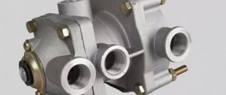
The relay valve is installed on the side member of the vehicle frame. The valve is secured with nuts screwed onto two elongated bolts connecting the upper and lower valve body.
1. Operating principle
2. Disassembly and valve assembly
3. Functionality check
4. Basic faults
Not available:
| № | Part code | Name | Part Information |
| 304183 | Hollow rivet | Quantity 2 Coated uncoated | Not available |
| 100-3512099 | Tablet | Quantity 1 Model 100 Group Brakes Subgroup Pressure regulator Part number 099 | Not available |
| 100-3537020 | Frame | Quantity 1 Model 100 Group Brakes Subgroup Manual brake valves Part serial number 020 | Not available |
| 100-3537027 | Stopper | Quantity 1 Model 100 Group Brakes Subgroup Manual brake valves Part serial number 027 | Not available |
| 484103 | Pin | Quantity 2 Coated uncoated | Not available |
| 100-3537091 | Washer | Quantity 1 Model 100 Group Brakes Subgroup Manual brake valves Part number 091 | Not available |
| 100-3537092 | Washer | Quantity 1 Model 100 Group Brakes Subgroup Manual brake valves Part serial number 092 | Not available |
| 100-3537093 | Washer | Quantity 1 Model 100 Group Brakes Subgroup Manual brake valves Part serial number 093 | Not available |
| 100-3537094 | Washer | Quantity 1 Model 100 Group Brakes Subgroup Manual brake valves Part serial number 094 | Not available |
| 100-3537025 | Ring | Quantity 1 Model 100 Group Brakes Subgroup Manual brake valves Part serial number 025 | Not available |
| 484102 | Pin | Quantity 2 Coated uncoated | Not available |
| 489302 | Resistant ring | Quantity 1 Coated uncoated | Not available |
| 100-3537052 | Spring | Quantity 1 Model 100 Group Brakes Subgroup Manual brake valves Part number 052 | Not available |
| 100-3537057 | Support washer | Quantity 1 Model 100 Group Brakes Subgroup Manual brake valves Part serial number 057 | Not available |
| 100-3537055 | Ring | Quantity 1 Model 100 Group Brakes Subgroup Manual brake valves Part serial number 055 | Not available |
| 100-3537054 | Valve body | Quantity 1 Model 100 Group Brakes Subgroup Manual brake valves Part serial number 054 | Not available |
| 100-3537056 | Valve ring | Quantity 1 Model 100 Group Brakes Subgroup Manual brake valves Part serial number 056 | Not available |
| 100-3537050 | Piston | Quantity 1 Model 100 Group Brakes Subgroup Manual brake valves Part number 050 | Not available |
| 100-3537044 | Ring | Quantity 2 Model 100 Group Brakes Subgroup Manual brake valves Part serial number 044 | Not available |
| 100-3537046 | Spring | Quantity 1 Model 100 Group Brakes Subgroup Manual brake valves Part serial number 046 | Not available |
| 100-3537095 | Washer | Quantity 1 Model 100 Group Brakes Subgroup Manual brake valves Part serial number 095 | Not available |
| 100-3537097 | Washer | Quantity 1 Model 100 Group Brakes Subgroup Manual brake valves Part serial number 097 | Not available |
| 100-3537042 | Spring plate | Quantity 1 Model 100 Group Brakes Subgroup Manual brake valves Part number 042 | Not available |
| 100-3537035 | Stock | Quantity 1 Model 100 Group Brakes Subgroup Manual brake valves Part number 035 | Not available |
| 100-3537043 | Washer | Quantity 1 Model 100 Group Brakes Subgroup Manual brake valves Part serial number 043 | Not available |
| 100-3537026 | Ring | Quantity 1 Model 100 Group Brakes Subgroup Manual brake valves Part serial number 026 | Not available |
| 100-3537048 | Spring | Quantity 1 Model 100 Group Brakes Subgroup Manual brake valves Part number 048 | Not available |
| 100-3537040 | Guide | Quantity 1 Model 100 Group Brakes Subgroup Manual brake valves Part number 040 | Not available |
| 489301 | Resistant ring | Quantity 1 Coated uncoated | Not available |
| 100-3537031 | Guide cap | Quantity 1 Model 100 Group Brakes Subgroup Manual brake valves Part serial number 031 | Not available |
| 100-3537036 | Washer | Quantity 1 Model 100 Group Brakes Subgroup Manual brake valves Part serial number 036 | Not available |
| 484104 | Pin | Quantity 1 Coated uncoated | Not available |
| 100-3537038 | Spring | Quantity 1 Model 100 Group Brakes Subgroup Manual brake valves Part serial number 038 | Not available |
| 100-3537062 | Video clip | Quantity 2 Model 100 Group Brakes Subgroup Manual brake valves Part serial number 062 | Not available |
| 302196 | Screw | Quantity 2 Coated uncoated | Not available |
| 100-3537061 | Washer | Quantity 2 Model 100 Group Brakes Subgroup Manual brake valves Part serial number 061 | Not available |
| 305887 | Spring washer 6 | Quantity 2 Coated uncoated | Not available |
| 305905 | Washer | Quantity 2 Coated uncoated | Not available |
| 100-3537060 | Lid | Quantity 1 Model 100 Group Brakes Subgroup Manual brake valves Part serial number 060 | Not available |
| 100-3537063 | Handle assembly | Quantity 1 Model 100 Group Brakes Subgroup Manual brake valves Part serial number 063 | Not available |
| 100-3537068 | Spring | Quantity 1 Model 100 Group Brakes Subgroup Manual brake valves Part serial number 068 | Not available |
| 100-3537066 | Guide | Quantity 1 Model 100 Group Brakes Subgroup Manual brake valves Part serial number 066 | Not available |
| 100-3537067 | Sleeve | Quantity 1 Model 100 Group Brakes Subgroup Manual brake valves Part serial number 067 | Not available |
| 489326 | Resistant ring | Quantity 1 Coated uncoated | Not available |
Principle of operation
Compressed air from air cylinders is supplied to input 1. Input 2 is connected to the brake valve of the parking brake system, and output 3 is connected to spring energy accumulators.
If there is no pressure in port 2, piston 9 is in its uppermost position. The inlet valve 11 is closed under the action of a spring, and the outlet valve 7 is open. Through the open exhaust valve, the cylinders of spring energy accumulators communicate with atmospheric outlet 4.
WATCH THE VIDEO
When compressed air is supplied from the brake valve to terminal 2, air enters cavity a. Piston 9, under the action of compressed air, moves downwards, closes the outlet valve 7 and opens the inlet valve 11 from the seat 10. The cylinders of the spring accumulators are filled with compressed air from air cylinders through outlet 1 and the open inlet valve 11. The pressure in outlet 2 is set in accordance with position of the brake valve handle.
The necessary proportionality of the control and input pressures is ensured by a stepped piston 9. When the pressure in port 3 reaches proportional to the pressure in port 2, the piston 9 moves upward until the intake valve 11, moving under the action of a spring, closes. When the pressure in the control line decreases, i.e. in terminal 2, piston 9, under the influence of higher pressure in terminal 3, moves upward and opens from exhaust valve 7. Compressed air from the spring accumulators escapes into the atmosphere through the open exhaust valve 7 and atmospheric terminal 4, pressing valve 1.
Parking and spare brake systems KAMAZ-4310
Military Encyclopedia - historical and archival military-patriotic portal
home☆Soviet military encyclopedia☆military equipment☆military science☆military review☆history of weapons☆forum
military equipment ☆ articles on the VAT device ☆
On the KamAZ-4310 vehicle, the parking and backup systems are combined together, i.e. have common brake mechanisms and a common pneumatic drive. The difference in brake systems is the way the hand brake valve is operated.
The braking mechanisms of these systems are the brake mechanisms of the service brake system installed in the wheels of the rear bogie. The pneumatic drive of the parking and spare brake systems includes four energy accumulators 28 (see Fig. 145 in previous materials), a single safety valve 16, two air cylinders 21, a brake valve 6, a two-line bypass valve 26, an accelerator valve 25, pipelines and hoses . The devices of this drive form the third circuit of the vehicle's pneumatic system.
Spring energy accumulators (see Fig. 152) are used to activate the brake mechanisms of the wheels of the rear bogie when using the parking or emergency brake systems. The energy accumulator is mounted on the brake chamber of the service brake system. Its main parts are cylinder 4, power spring 5 with piston 3, pusher 2, screw 6 with thrust bearing 8.
When the car moves, compressed air is supplied to the cavity of the cylinder 4, acts on the piston 3 and compresses the spring 5. In this case, the pusher 2 does not act on the diaphragm 9 of the pneumatic chamber, the brake mechanisms are in the braked state.
When braking with a parking or western brake system, compressed air exits the cylinder cavity into the atmosphere, the power spring expands, and its force through pusher 2 and rod 10 activates the brake mechanisms.
Single safety valve 16 (see Fig. 145) is designed to maintain pressure in the air cylinders of the third circuit in the event of an emergency decrease in pressure in the compressed air supply system for drives. The valve (Fig. 153) consists of a body 1 with a cover 5, a piston 4 with a diaphragm 3, and a check valve 2.
Fig. 153. Single safety valve : a - position when the pressure in the system is below 550 kPa; 6 — working position; I - output to the condensation cylinder; II - output to the cylinder of the third kennel; 1 - body; 2 - check valve; 3 - diaphragm; 4 - piston; 5 - cover; 6, 7 — springs; 8 — adjusting screw.
Compressed air from the condensation cylinder enters through outlet 1 into cavity A under the diaphragm. When the set pressure is reached (530 kPa), diaphragm 3 rises and air passes into cavity B, from where the 2nd outlet II passes through the check valve into the third circuit cylinders. When the pressure in terminal 1 decreases, diaphragm 3 lowers onto the seat and separates terminals I and II, while check valve 2 closes and prevents the reverse movement of air from terminal II to terminal 1. Air cylinders 21 (see Fig. 145) of the third circuit with a total capacity 40 l, have taps for draining condensate and pressure drop sensors.
Rice. 154 Manual brake valve : a - device; b — inhibited positions; c — position during braking; I - output to air cylinders; II - release into the atmosphere; III - output to the spring energy accumulator through the accelerator valve; 1 - valve spring; 2 - body; 3 - balancing spring; 4 — rod spring; 5 — figured ring; b — cap spring; 7 — cover with handle; 8 — guide cap; 9 — rod; 10 — exhaust valve; 11 — follower piston
Brake valve 6 is used to control the spring energy accumulators of the drive of the parking and spare brake systems. The valve is a single-section, reverse-acting valve with a piston follower mechanism and a manual drive, located in the cabin. The main parts of the valve are body 2 (Fig. 154), cover 7 with a handle, follower piston 11, outlet valve 10, rod 9, figured ring 5, guide cap 8, balancing spring 3 springs 1, 4 and 6, respectively, valves, rod and cap. Input I is connected to the air cylinders of the circuit, output II is connected to the atmosphere, output III is connected through an accelerator valve with energy accumulators,
In the released state, the valve handle, together with the cap 8 and the rod 9, is in the lowest position under the action of the spring. The exhaust valve 10 is torn from the seat in the piston 11 by the rod 9, thereby the valve disconnects pin I from the atmospheric port II and communicates pin 1 with pin II. Compressed air passes through the hole in the follower piston into cavity A and through the window between the bottom of the piston 11 and the valve 10 in cavity B and further along the channel to terminal III and to the accelerator valve. The latter supplies compressed air to the cylinders of energy accumulators.
When braking, the valve handle turns upward, together with the cover 7, the cap 8 rotates, which slides along the screw surfaces of the figured ring 5 and carries the rod 8 with it. The lower edge of the rod opens from the valve, which, under the action of a spring, sits on the seat in the piston 11, disconnecting the output I from terminal III and connecting terminal III with atmospheric terminal II. Compressed air from the accelerator valve line escapes into the atmosphere, which leads to operation of the valve, which releases compressed air from the cylinders of the energy accumulators into the atmosphere. The brake valve has a follower effect. As the compressed air escapes into the atmosphere, the pressure in cavity B drops, the follower piston 11 rises under the action of its spring and the valve 10 sits on the edge of the rod 9, after which the release of air from the accelerator valve line stops.
In the rearmost position, the crane handle is secured with a locking latch. In this case, the compressed air completely escapes into the atmospheric outlet VI, since the piston 11 rests against the spring limiter 4 and the valve 10 does not reach the edge of the rod 9. In this case, the system operates as a parking one. In intermediate positions of the handle, thanks to the following action of the crane, the system can work as a spare one.
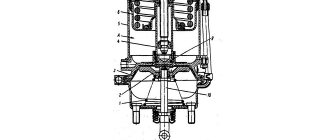
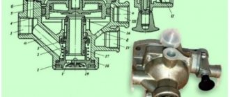
Accelerator valve 25 (see Fig. 155) serves to reduce the response time of the spare brake system and to release compressed air from the energy accumulator into the atmosphere. The valve (Fig. 155) is installed inside the right side member of the frame at a minimum distance from the energy accumulator and consists of an upper and lower housing, a piston 3, an inlet valve 4 and an outlet valve 1 with a spring 5 on a common rod. The cavity above the piston forms control chamber 2. Compressed air is supplied to terminal III from the cylinders of the third circuit, terminal IV is connected to the brake valve, terminal 1 is connected to the energy accumulator cylinders, terminal II is connected to the atmosphere.
Fig. 155. Accelerator valve : a - device; b — inhibited position; c — position during braking; I - output to the energy storage cylinders; II - atmospheric output; III - output to the air cylinder; I — output to the manual brake valve; 1 - exhaust valve; 2 - control, camera; 3 - piston; 4 — inlet valve; 5 – spring
In the initial position in the cavity Au in the control chamber, the same pressure is established, since compressed air is supplied here from the same air cylinders. The area of the upper part of the piston 3 is larger than the lower part, as a result of which it goes down, while the outlet valve 1 is closed and the inlet valve 4 is open. Compressed air from terminal III (from the air cylinders) passes to terminal 1 (to the energy accumulators).
When braking, compressed air from the control chamber escapes into the atmosphere through the manual brake valve, piston 3 moves upward, exhaust valve 1 opens, and exhaust valve 4 closes under the action of spring 5. Compressed air from energy accumulators exits to the atmosphere through valve 1 and outlet P.
When the brake is released, compressed air is supplied through port IV from the brake valve to control chamber 2. Piston 3 moves down and first closes exhaust valve 1, then opens inlet valve 4. Compressed air from port III passes through valve 4 and port I to the energy accumulators.
The relay valve has a follower effect. When braking, as air leaves the energy accumulators into the atmosphere, the pressure in cavity A drops and, when it becomes less than in control chamber 2, piston 3 moves down and exhaust valve 1 closes. Thus, the air pressure in the energy accumulators is set in proportion to the pressure in the control line (and therefore, the position of the hand brake valve handle). Similarly, when the brake is released, as the pressure in cavity A increases, the piston moves upward and the inlet valve 4 closes.
Double-line bypass valve 26 (see Fig. 155) is designed to supply (or release) compressed air to energy accumulators from two independent circuits. The valve (Fig. 156) consists of a body 3, a cover 1, a membrane 2 and an o-ring. The line from the accelerator valve is connected to terminal I, the power accumulator line is connected to terminal II, and the emergency brake release valve line is connected to terminal III.
When the car is released using a manual brake valve, compressed air from the air cylinders is supplied to terminal 1 through the accelerating valve, presses the membrane against the seat of cover 1 and passes through terminal P to the energy accumulators. When the car is released using the emergency brake release valve, the membrane is pressed against the housing seat 3. When the car is braked, the membrane remains pressed to the seat to which it has moved, and air passes through terminal II to terminals I or III. When compressed air is simultaneously supplied to terminals I and III, membrane 2 takes the middle position.
To monitor the condition of the drive of the parking and reserve brake systems, two pressure sensors are provided (on the air cylinder and in the energy accumulator line) with warning lights on the instrument panel. One light indicates a drop in pressure in the cylinder, the second indicates that the car is braking with the parking brake. In addition, there are two control valves in the circuit.
Rice. 156 Double-line bypass valve : a - initial position; b - air supply from the accelerator valve; I - output to the accelerator valve; II - output to energy accumulators; III - output to the emergency brake release valve; I - cover; 2 - membrane; 3 - body.
Drive operation. Air cylinders 21 (see Fig. 155) of the third circuit are filled with compressed air from the general supply system through a single safety valve 16. When the pressure in the cylinders reaches 550 kPa, the signal light of the circuit goes out.
When braking with the parking brake, the valve handle 6 is in the upper (rear) position; The line running from the tap to the accelerating valve 25 is connected to the atmosphere. In the accelerator valve, the exhaust valve is open and the cylinders of the energy accumulators are also connected to the atmosphere. The power springs of the energy accumulators activate the brake mechanisms of the wheels of the rear bogie.
When releasing the brakes after stopping or parking, the driver lowers the crane handle b down. Compressed air from the drive cylinders passes through the tap into the control chamber of the accelerator valve 25, in which the inlet valve opens and compressed air from the same cylinders, but through short and larger diameter pipelines, is supplied through the accelerator and dual-line valves 26 into the cylinders of the energy accumulators. The power springs of the latter are compressed and the brake mechanisms of the rear bogie wheels are released.
If it is necessary to use the emergency brake system, the driver operates the brake valve handle. The drive operates in the same way as during parking braking. The effectiveness of such braking is determined by the position of the crane handle and is generally lower than braking by the service brake system, approximately two times.
In the event of an emergency drop in pressure in the parking brake drive, the energy accumulators are activated and the car stops. In order to release the brakes in this condition, an emergency brake release system is provided. The main element of such a system is push-button valve 5 (see Fig. 145) installed in the cockpit under the instrument panel.
Rice. 157. Pneumatic push-button valve : I - output to air points; II - atmospheric output; III - output to a two-line valve; 1 - body; 2 - filter; 3 — button; 4 - pusher; 5 — exhaust channel; 6 - valve; 7 — valve spring.
Compressed air is supplied to valve outlet I (Fig. 157) from secondary circuit cylinders, outlet II is connected to the atmosphere, outlet III is connected to a two-line valve. When you press the valve button 3, the inlet valve 6 opens, and the channel 5 of the pusher 4 closes. Compressed air from the secondary circuit cylinders passes through a two-line valve into the cylinders of the energy accumulators, which leads to the release of the brakes on the wheels of the rear bogie. When the button is released, pusher 4 returns to its original position under the action of a spring, and inlet valve 6 closes. Compressed air from the connecting pipelines to the two-line valve (and in the absence of pressure in the air cylinders of the parking brake system and from the cylinders of energy accumulators) exits through the valve into the atmosphere.
In the absence of compressed air and in the second circuit, the car can be released using a mechanical release device, which is built into the cylinders of the energy accumulators. To do this, screws 6 (see Fig. 152) must be screwed in until they stop in each energy accumulator.
It is prohibited to operate a vehicle with faulty parking and emergency brake systems.
Tags: KAMAZ 4310 ☆ brake systems ☆ vehicle design ☆
| Working brake system of the KAMAZ-4310 vehicle < Prev. | Track. > Auxiliary braking system KamAZ-4310 |
Podolsk tow truck
In Moscow and Moscow region
- Contacts:
- +7
- around the clock
- seven days a week
© Military Encyclopedia. Map of site.
Disassembly assembly
Place the valve in a vice with the atmospheric outlet facing up and clamp the body. Remove locking ring 10 with round pliers and remove guide cap 3, spring 11 and body 4 with valves 5 and 8 from body 2.
Unscrew the bolts 12 and remove the housing 2. To dismantle the piston 7, it is necessary to supply air under a pressure of 0.05 MPa at port 2, covering the piston 7 with your hand on top.
After disassembling the accelerator valve parts, they must be washed, dried and inspected. Cracks, chips and other noticeable defects are not allowed on the surface of body parts. Parts must be cleaned of rust and dirt. All rubber parts must be replaced with new ones.
Before assembling the valve, the parts must be lubricated with Ciatim -221 lubricant. The valve assembly and rubber rings must be carefully installed without damage. The valve is reassembled in the reverse order of disassembly.
Valves, rubber O-rings and other rubber parts must be assembled carefully to avoid damaging them. The presence of scratches, cuts and other defects on the surface of these parts is not allowed.
100-3537010 Reverse action brake valve - KamAZ-65115 (Euro-3):
1 2 3 4 5 6 7 8 9 10 11 12 13 14 15 16 17 18 19 19 20 21 22 23 24 25 26 27 28 29 30 31 32 33 34 34 35 35 36 36 37 37 38 38 39 40 41 42 43 44
List of components from 100-3537010 Reverse action brake valve for KamAZ-65115 (Euro-3)
Parts diagrams are for reference purposes only! We do not sell all spare parts from 100-3537010 Reverse-action brake valve for KamAZ-65115 (Euro-3) presented in this list. If there is a “Show prices” link in the right column, these spare parts from “100-3537010 Reverse Brake Valve” are on sale. Availability in warehouses for details and prices, see the product card. If there is no “Show cost” link in the right column, we do not sell such parts and do not accept orders for them.
| № | Part code | Name | Part Information | Show all prices |
Checking the relay valve for functionality.
Install the valves on the test bench and connect according to the diagram shown in Fig. 11.50
Apply air at a pressure of 0.75 MPa (7.5 kts/cm2) to terminal 1. Supply and release air three times at a pressure of 0.75, MPa (7.5 kgf/cm2): terminal 2. Air pressure at terminal 3; should vary from zero to 0.75 MPa (7.5 kgf/cm2) Increase the pressure in terminal 11 from zero to 0.030...0.045 MPa (0.30...0‚45 kgf/cm2), in this case: pressure should appear at terminal 111 .
When the pressure in outlet C reaches 0.66...0.7 MPa (6.6...7.0 kgf/No. 2), the pressure >: outlet 1 should become 0.73 MPa (7.3 kf/em2). When the pressure in terminal I drops to zero, the pressure in terminal 111 should also drop to zero.
Basic valve malfunctions.
- When you turn on the handbrake, the parking system releases all the air. The reason is that the valve is jammed when venting air. The valve jams due to accumulated dirt and dust through the lower boot of the accelerator valve.
- It leaks air from under the valve. Freezing of condensate inside the valve, wear of rubber cuffs.
WATCH THE VIDEO
Source
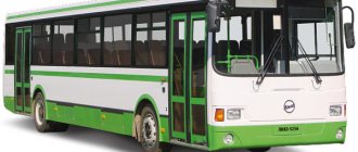
KamAZ 53212 1985, 260 l. With. — tuning
Cars for sale
Renault Fluence, 2010
Lada Granta, 2016
Nissan Note, 2012
Mitsubishi Lancer, 2005
Comments 32
smart thing, you need to do it yourself
Hello, did you also insert a tee into the feed for ynnrgachi?
Yeah, but I took it from someone else
Hi, where is your brake switch? (frog)
I don’t even know, I have a homemade spring under the pedal and a positive wire on it
I can’t take a photo, but I can draw a diagram
Can you post a diagram of a homemade frog?!
Well, I finally found how to do this! Otherwise, everything is new and it’s only slowing down in front! I just have a small question, could you write everything down in detail and add pictures? Well, it’s really necessary! Thank you in advance!)))
It’s already described in detail here, you buy a copper tube, the ends to it (it’s more convenient to work with it), you take the accelerator valve from the handbrake, put it between the front gearbox and the balancer axis as in 1 photo on the left side, then the tube that comes from the GTK (main brake valve ) you cut a tee into it as in 1 photo and connect it upward to the accelerating valve (This will include an additional air supply), the air supply tube from the accelerating valve to the power generators along the line from the State Customs Committee will need to be left as it was (3 photo), Now you need bring the air from the receiver to the accelerator valve (connected at the bottom), I took it from the right front receiver (4th photo), Next we need to bring the air from the accelerator valve to the energy pumps (2nd photo). Well, it seems that when we press the brake, the accelerator valve turns on and it takes additional air from the additional receiver. If you have any questions, ask))