The UAZ 469 gearbox is used to change the torque from the engine through the clutch. The UAZ 469 gearbox converts the rotational energy of the crankshaft into forward motion of the transmission. Thanks to the four gears that the gearbox has for moving forward and one in reverse, energy is transferred to the wheels. The car can move in any direction. The UAZ 469 transmission is divided into two types according to the type of gearbox - old model and new model.
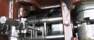
Gearbox UAZ 469
Photo 1: UAZ 469 checkpoint (Source: Yandex.Pictures)
General characteristics
All UAZ gearboxes are similar in design and functioning. Only gearboxes manufactured by Hyundai-Dymos, Korea, differ greatly. These are gearboxes for the UAZ Patriot and UAZ Hunter models of the 452nd and 469th configurations. The company produces five-speed gearboxes, synchronized in all four forward gears.
The boxes produced by Russian manufacturers are unified and can mutually replace each other. In the Russian Federation, the UAZ 469 gearbox is produced by two enterprises. The first is Avtodetal-Service OJSC (ADS), Ulyanovsk and the second is AMZ JSC, Arzamas.
Both companies produce UAZ gearboxes, in Ulyanovsk four-speed with synchronizers in third and fourth gears, four-speed and five-speed with synchronizers in all forward gears. Five-speed, fully synchronized gearboxes are produced in Arzamas.
The fourth supplier and manufacturer of gearboxes for UAZ 469 vehicles is the partner company ADS OJSC, Ulyanovsk, under the EXPERT brand, China. It supplies five-stage, fully synchronized automotive gearboxes to the main conveyor belt of the assembly plant in Ulyanovsk.
The principle of all-wheel drive on the UAZ Patriot
It is known that all-wheel drive on a car is a pleasant addition to mainly SUV vehicles, with the help of which you can get out of any swamp. But the downside of this phenomenon has always been considered to be greater fuel consumption when this system is turned on. The main advantages of this system are:
- better grip of the vehicle with the road;
- motor efficiency;
- fast start;
- increased power;
- cross-country ability increases;
- better handling parameters.
Among the disadvantages, in addition to the doubled fuel consumption, one can also note the complex design of this system, which entails a considerable cost of the device.
UAZ 469 gearbox device
The UAZ 469 gearbox has the following device:
- input shaft;
- bearing cover;
- input shaft cuff;
- retaining ring;
- input shaft ball bearing;
- secondary shaft roller bearing;
- input shaft spline;
- locking ring;
- synchronizer clutch for 3rd-4th gears;
- coupling hub;
- key;
- 3rd gear spline;
- third gear;
- gear bushing;
- 2nd gear gear;
- crankcase;
- 2nd gear spline;
- synchronizer clutch for 2nd-1st gears;
- 1st gear spline;
- 1st gear gear;
- 1st gear gear bushing;
- secondary shaft roller bearing;
- secondary shaft bushing;
- 5th gear driven gear;
- 5th gear housing;
- double row ball bearing of the secondary shaft;
- spline washer;
- retaining ring;
- secondary shaft;
- bolt;
- support ring;
- 5th gear drive gear;
- splined ring of the 5th gear drive gear;
- synchronizer spring;
- synchronizer block;
- 5th gear synchronizer clutch;
- intermediate shaft ball bearing;
- reverse gear roller bearing;
- reverse gear;
- reverse gear axis;
- gear block for drive of the intermediate shaft and 3rd gear;
- intermediate shaft;
- intermediate shaft roller bearing;
- bearing cover.
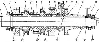
UAZ 469 gearbox diagram
Photo 2: Diagram of the UAZ 469 checkpoint (Source: Yandex.Pictures)
The old-style UAZ 469 gearbox diagram is shown in the top figure. All the main spare parts for the UAZ 469 gearbox and gearbox components are clearly shown here. Products such as boot, oil seal, rubber seals are consumables and are replaced as they wear out. For the UAZ 469 car, the diagram is typical.
The gearbox in the UAZ 469 is attached to the clutch housing with four studs screwed into it. The drive gears of the intermediate shaft, second and third gears are made with helical teeth, the first gear - with straight teeth.
The gears are located on shafts and are in constant mesh. The gears of the first, second and third gears are mounted on the driven shaft on needle bearings. The drive shaft 1 has two supports. The front bearing is located in the crankshaft housing, the rear bearing is located in the front wall of the gearbox housing.
Operating principle
The old-style UAZ 469 gearbox is designed so that to engage 1st gear, the driver needs to move the upper end of the lever 37 with the knob forward and towards himself. After such manipulation, the lower end of the lever enters the transfer head of the 1st gear rod 56, moving it back. The force is transmitted through the fork 49 to the sliding clutch of the synchronizer 12.
It moves along the carriage splines and engages with the ring gear 13 of the first gear of the secondary shaft 16. From the primary shaft 1, torque is transmitted to the drive gear of the intermediate shaft 23. Then through the 1st gear of the intermediate shaft - to gear 13 of the 1st gear of the secondary shaft 16. These two pairs of gears significantly increase torque by reducing the speed of the secondary shaft.
From the gear 13 of the 1st gear of the secondary shaft, torque is transmitted through the ring gear to the synchronizer clutch 12 and then through the carriage to the secondary shaft 16. From the secondary shaft, the torque is transmitted through the splines to the transfer case and then to the transmission units.
When 2nd gear is engaged, synchronizer clutch 12 moves forward. Its internal teeth engage with the ring gear of gear 11. Through the drive gears of the intermediate shaft, then through the 2nd gear of the intermediate shaft, the torque is transmitted to the 2nd gear of the secondary shaft.
From the 1st gear gear of the secondary shaft, torque is transmitted through a ring gear to the synchronizer clutch. The next stage is through the carriage and then onto the secondary shaft.
3rd gear is engaged when the driver moves the synchronizer clutch 9 to the rear position. Gear 10 of the 3rd gear enters its shaft through the hub and synchronizer clutch. Through gear 10, torque is transmitted to synchronizer 9. Then, under the influence of torque, it enters secondary shaft 16.
The 4th gear operates at the moment when the synchronizer clutch 9 connects the primary 1 and secondary 16 shafts to each other. Torque is transmitted directly from one shaft to another, without intermediaries.
Reverse gear is designed in such a way that to engage it, the UAZ 469 gearbox lever must move forward the reverse intermediate gear 25. It engages with its teeth with the reverse gear of the intermediate shaft 23. At the same time, engagement is also carried out with the synchronizer ring gear 12.
Through the intermediate shaft gear 23, the torque is transmitted to the reverse intermediate gear 25. From there, the torque passes to the synchronizer ring gear 12. Next, it engages the secondary shaft 16. In total, when the 3rd gear is turned on, three pairs of gears operate, and the primary and secondary shaft perform multidirectional rotation.
Transmission feature
The old-style and new-style boxes have some minor differences. Old-style UAZ 469 gearbox:
All vehicles of the UAZ passenger car range are equipped. The input shaft is manufactured with a thickness of 35 mm.
Used on UAZ 469, 31512, 31514 vehicles.
Weight 36.5 kg.
Installed in UAZ trucks.
Used on vehicles UAZ 452, 3303,3909 (farmer), 3962 (sanitary van), 2206 (bus), 3741 (manufactured goods van).
The weight of the UAZ 469 transfer case is 34 kg.
New type of gearbox UAZ 469:
Applicability: UAZ passenger cars.
UAZ 469, 31512, 31514 vehicles are equipped.
The UAZ 469 gearbox is a gearbox with synchronizers in all gears.
Applicability – cargo vehicles UAZ 452, 3303,3909 (farmer), 3962 (nurse), 2206 (bus), 3741 (manufactured goods van).
The box on the UAZ 469 has such varieties. The price of units in the capital's markets and portals for the sale of automobile catches and parts, depending on the configuration, manufacturer and design, ranges from 15 to 25 thousand rubles. In Russian regions, the price of a gearbox for a UAZ 469 can range from 8 to 12 thousand rubles.
How to turn on a lowered UAZ loaf
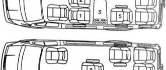
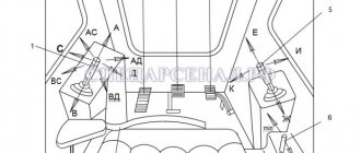
This page shows photos of the UAZ loaf car interior: Location of controls
1 - steering wheel. The steering wheel of UAZ-31512, UAZ-3153 and the UAZ-3741 family vehicles has a central horn button. The steering wheel of UAZ-31514 and UAZ-31519 cars is equipped with an energy-intensive pad and has two horn buttons located in the wheel spokes. 2 — rear view mirror (internal). Adjustable by turning around the articulated head. 3 - instrument panel. 4 — sun visors. 5 — windshield blower pipes. 6 — passenger handrail. 7 — lamp (plafond) lighting. 8 - battery ground switch. Switching the “mass” on and off is done by turning the knob 90°. 9 — lever for engaging the front drive axle. It has two positions: front - the axle is on, rear - the axle is off. Before engaging the front axle, engage the front wheels. Turn on the axle while the vehicle is moving. 10 - heater. 11 — transfer case control lever. It has three positions: forward - direct gear is engaged, middle - neutral, reverse - downshift is engaged. Before downshifting, engage the front axle. Engage the downshift with the clutch disengaged and only when the car is completely stopped. 12 — gear shift lever. The switching pattern is shown on the handle. Shift gears by smoothly pressing the lever without jerking. If you cannot engage the required gear before moving off, lightly release the clutch pedal, and then disengage the clutch a second time and engage the gear. When switching from a higher gear to a lower one, it is recommended to disengage the clutch twice and briefly press the throttle pedal. Engage reverse gear only after the vehicle has come to a complete stop. When you engage reverse, the reversing light turns on. 13 — lever of the parking brake system. To turn the lever on, move it back; to turn it off, press the button at the end of the lever and move the lever forward until it stops. When the parking brake is engaged, the red warning lamp on the instrument panel lights up. 14- handle for driving the hatch cover for ventilation and heating of the body. 15 — valve handle for switching fuel tanks. The handle is turned forward - the valve is closed, turned to the left - the left tank is on, turned to the right - the right tank is on. The valve is not installed on vehicles with one fuel tank. 16 — carburetor throttle control pedal. 17 — pedal of the service brake system. Brake the car smoothly, gradually increasing pressure on the pedal. When braking, do not let the wheels slide, as in this case the braking effect is significantly reduced (compared to rolling braking) and tire wear increases. In addition, strong and sudden braking on a slippery road can cause the car to skid. 18 — clutch pedal. When changing gears and starting from a stop, the clutch pedal should be pressed quickly and fully, and released smoothly. Depressing the pedal slowly or incompletely causes the clutch to slip, making it difficult to shift gears and causing increased wear on the clutch plate. When the pedal is suddenly released (especially when starting from a standstill), the load on the transmission increases, which can lead to deformation of the clutch driven disc and other transmission parts. When driving the car, do not keep your foot on the clutch pedal, as this leads to partial disengagement of the clutch and the disc slipping. 19 — foot switch for headlights. By pressing the button, with the headlights on, the low beam or high beam headlights are turned on. Not installed on vehicles with multifunctional left-hand stalks. 20 - portable lamp socket. 21 — radiator shutter control handle. Under certain operating modes and climatic conditions, in order to maintain the temperature of the engine coolant within 70-80 ° C, it is necessary to regulate the amount of air cooling the radiator using blinds. When the handle is pulled, the blinds close. 22 — rear view mirror (external). 23 — direction indicator switch handle. The handle automatically returns to the neutral position when the steering wheel is turned in the opposite direction (when the car enters a straight line). Some cars are equipped with multifunction steering column switches. 24 - carburetor throttle control knob. The extended handle is fixed by turning 90° in any direction. 25 - carburetor choke control handle. The extended handle is fixed by turning 90° in any direction.
Gearbox wear and repair
In what cases does the operation of a machine entail wear and tear on parts of the box, resulting in the need for repairs?
- Using a car in extreme conditions.
- Operation of a UAZ 469 with a faulty clutch.
- Using low-quality oils for the drive axle.
- Carrying out maintenance of the gearbox by a non-professional.
These are the main prerequisites that may cause urgent repairs of the UAZ 469.
To repair a gearbox you need a large set of equipment.
- Open-end wrenches in 2 copies (for 10, 12, 13, 14, 17, 19, 22). Using a 14 wrench you need to unscrew the rear shaft from the transfer case flange. If you use this key incorrectly, you can create huge problems for yourself.
- Socket wrenches.
- Professional wrench for flat nuts.
- Regular and Phillips screwdrivers.
- Duckbills for removing and putting on circlips.
- Metal pin for knocking out individual parts.
- To quickly unscrew nuts and bolts, you need a small piece of iron pipe.
- High quality core and chisel.
- Mounting blade.
- Heavy hammer.
- A large number of cans for bolts and nuts to sequentially place parts during work.
- Bearing puller.
- A car owner who pays attention to his car can identify problems with the gearbox.
What should alert an experienced driver?
If noises appear in the gearbox that were not previously heard, then at this stage it is necessary to diagnose the gearbox and, if necessary, repair it. If the noise reoccurs, it is advisable to pay attention to the bearings and possibly replace them. If noise occurs in a particular gear, then most likely the cause is worn gears.
Synchronizers can fail if your car has rough gear shifting. The next reason may be a decrease in the oil level in the crankcase or its absence. Repairing the box requires high-quality preparation of parts, grinding and boring them. This is a complex process, not everyone can do such work themselves.
Before moving on to repairing the UAZ 469 gearbox, you need to study the relevant literature. Don’t just look, but read and pay attention to what is said about the left-hand thread, the location of washers, stops and small details. To remember the chronological sequence of actions during the repair process, you can make a cheat sheet for yourself.
For car gaskets, it is advisable to purchase imported sealant. It is of better quality and more reliable. To lubricate rotating parts, it is best to use Litol - this is the most affordable product.
Repair of the gearbox can only be entrusted to a highly qualified specialist who has professional tools, knows the structure and diagrams of the UAZ 469 gearbox and is able to carry out repairs in the shortest possible time.
Source
Repair of UAZ Bukhanka transfer case
Serious repairs to the UAZ transfer case are rarely performed. As a rule, to restore normal operation, adjusting the product and lubricating problem areas is enough. If repairs cannot be avoided, then the operation to return the box to its former functionality is done in strict order.
- Dismantling the transfer case;
- Disassembling the transfer case;
- Fault detection;
- Troubleshooting (replacement, restoration of parts);
- Transfer case assembly;
- Installing the transfer case in place;
- Functionality check and configuration.
Before carrying out work, select the necessary tools; for this, find out the type and type of transfer case. Functionally, repair is the replacement of damaged parts with new ones, for this reason more attention is paid to the rejection stage.
- Oil seals (changed during disassembly, regardless of the degree of wear);
- Gears (parts cannot be repaired due to the loads they experience);
- Forks and splines (elements affect the quality of work and safety);
- Bearings;
- Protective casing (if cracks or chips are detected, the part is replaced).
UAZ transfer case control mechanism:
UAZ Bukhanka transfer case control
The UAZ Bukhanka transfer case is controlled remotely from the driver’s cab. The levers used to manipulate the car are located on the right side of the user. The upper rod activates and deactivates the front pair of wheels of the car, has two positions: top (the bridge is activated), bottom (the bridge is deactivated).
Position of the transfer case levers of the UAZ Bukhanka:
The location of the transfer case levers on the UAZ Bukhanka is possible in three options. First, the main gear is activated, middle (zero), the main shaft does not rotate, second, low gear is activated.
In order to avoid damage to the transfer case if the gear is incorrectly activated, a locking device is provided. The product is fixed in the cover of the gear change rods. Thanks to the fuse, the low gear is activated after the front pair of wheels is activated. Meanwhile, the front pair of wheels is not activated when a downshift is engaged. A solution has been implemented with a ball acting as a lock. The sphere in the cover prevents the rods from moving and deactivates the front pair of wheels until the rods are put into downshift. The lock prevents the driveshaft and rear pair of wheels from being overloaded.
There are single-lever control elements, one rod alternately activates: the front pair of wheels, zero, then low stage.
The need to diagnose the UAZ model 452 gearbox
This vehicle must be diagnosed if control begins to deteriorate, characteristic creaks are heard when a gear change occurs, or gears begin to change spontaneously. The UAZ transfer case should be checked if the grip of the wheels on the road has noticeably deteriorated, a hum or increasing noise has begun to appear during its operation.
During maintenance, technicians must check the system for oil leaks and lubricant levels. All worn parts in the transmission system must be replaced with new ones. Also, diagnostics involves lubricating the lever axle and adjusting the front linkages.
Routine diagnostics in a professional auto repair shop allows you to accurately determine the existing nature of the problem with the gearbox and eliminate existing problems at an early stage.
How to change gears on a UAZ Bukhanka?
This page contains photos of the interior of the UAZ Bukhanka car:
Location of controls
1 – steering wheel. The steering wheel of UAZ-31512, UAZ-3153 and the UAZ-3741 family vehicles has a central horn button. The steering wheel of UAZ-31514 and UAZ-31519 cars is equipped with an energy-intensive pad and has two horn buttons located in the wheel spokes. 2 – rear view mirror (internal). Adjustable by turning around the articulated head. 3 – instrument panel. 4 – sun visors. 5 – windshield blower pipes. 6 – passenger handrail. 7 – lighting lamp (plafond). 8 – battery ground switch. Switching the “mass” on and off is done by turning the knob 90°. 9 – lever for engaging the front drive axle. It has two positions: front – the axle is on, rear – the axle is off. Before engaging the front axle, engage the front wheels. Turn on the axle while the vehicle is moving. 10 – heater. 11 – transfer case control lever. It has three positions: forward – direct gear is engaged, middle – neutral, reverse – downshift is engaged. Before downshifting, engage the front axle. Engage the downshift with the clutch disengaged and only when the car is completely stopped. 12 – gear shift lever. The switching pattern is shown on the handle. Shift gears by smoothly pressing the lever without jerking. If you cannot engage the required gear before moving off, lightly release the clutch pedal, and then disengage the clutch a second time and engage the gear. When switching from a higher gear to a lower one, it is recommended to disengage the clutch twice and briefly press the throttle pedal. Engage reverse gear only after the vehicle has come to a complete stop. When you engage reverse, the reversing light turns on. 13 – lever of the parking brake system. To turn the lever on, move it back; to turn it off, press the button at the end of the lever and move the lever forward until it stops. When the parking brake is engaged, the red warning lamp on the instrument panel lights up. 14- handle for driving the hatch cover for ventilation and heating of the body. 15 – valve handle for switching fuel tanks. The handle is turned forward - the valve is closed, turned to the left - the left tank is on, turned to the right - the right tank is on. The valve is not installed on vehicles with one fuel tank. 16 – carburetor throttle control pedal. 17 – pedal of the service brake system. Brake the car smoothly, gradually increasing pressure on the pedal. When braking, do not let the wheels slide, as in this case the braking effect is significantly reduced (compared to rolling braking) and tire wear increases. In addition, strong and sudden braking on a slippery road can cause the car to skid. 18 – clutch pedal. When changing gears and starting from a stop, the clutch pedal should be pressed quickly and fully, and released smoothly. Depressing the pedal slowly or incompletely causes the clutch to slip, making it difficult to shift gears and causing increased wear on the clutch plate. When the pedal is suddenly released (especially when starting from a standstill), the load on the transmission increases, which can lead to deformation of the clutch driven disc and other transmission parts. When driving the car, do not keep your foot on the clutch pedal, as this leads to partial disengagement of the clutch and the disc slipping. 19 – foot switch for headlights. By pressing the button, with the headlights on, the low beam or high beam headlights are turned on. Not installed on vehicles with multifunctional left-hand stalks. 20 – portable lamp socket. 21 – radiator shutter control handle. Under certain operating modes and climatic conditions, in order to maintain the temperature of the engine coolant within 70-80 ° C, it is necessary to regulate the amount of air cooling the radiator using blinds. When the handle is pulled, the blinds close. 22 – rear view mirror (external). 23 – turn signal switch handle. The handle automatically returns to the neutral position when the steering wheel is turned in the opposite direction (when the car enters a straight line). Some cars are equipped with multifunction steering column switches. 24 - carburetor throttle control knob. The extended handle is fixed by turning 90° in any direction. 25 - carburetor choke control handle. The extended handle is fixed by turning 90° in any direction.
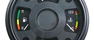
Console:
1 – alarm switch. When you press the switch button, the lamps of all indicators and turn signal indicators, the signal lamp for turning on the turn indicators (item 6) and the indicator lamp inside the switch button simultaneously operate in a flashing mode. 2 – speedometer. It shows the speed of the car in km/h, and the counter installed in it shows the total mileage of the car in km. 3 – fuel level indicator in the tank. Each tank has its own indicator sensor (except for additional tanks). 4 – warning lamp for emergency condition of the brake system (red). Lights up when the tightness of one of the hydraulic drive circuits to the brake mechanisms is broken. 5 – warning light for turning on the parking brake (red). 6 – signal lamp for turning on the direction indicators (green). Operates in flashing mode when the turn signal switch or hazard warning light switch is turned on. 7-signal lamp for emergency overheating of the coolant in the radiator. 8 – signal lamp for turning on the high beam headlights (blue). 9 – coolant temperature indicator in the engine cylinder block. 10-signal lamp for emergency oil pressure. Lights up when the oil pressure in the engine lubrication system drops to 118 kPa (1.2 kgf/cm2) 11 – oil pressure indicator in the engine lubrication system. 12 – voltmeter. Shows the voltage in the vehicle's on-board network. 13 – cigarette lighter. To heat the cigarette lighter coil, press the handle of the insert, push it in until it locks into the body and release the handle. When the required heating temperature of the spiral is reached, the insert automatically returns to its original position. Forced holding of the insert in a recessed position is not allowed. 14 – lighting lamp (installed on UAZ-31512, on other models a courtesy lamp is installed) 15 – lighting lamp (plafond) switch. On some models the switch is located next to the lampshade. 16 – carburetor throttle control handle. 17 – switch for fuel level sensors in tanks. 18 – rear fog lamp switch with built-in warning light 19 – fog lamp switch. 20 – combined ignition and starter switch (see Fig. 1.22 and 1 23). The key from the ignition switch of UAZ-31514, UAZ-31519, UAZ-3153 vehicles is removed only in position III, and the locking mechanism is activated, blocking the steering shaft. To lock the steering when parked, set the key to position III, remove it and turn the steering wheel in any direction until you hear a click, indicating that the tongue of the locking device coincides with the groove of the steering wheel shaft locking sleeve. When unlocking the steering, insert the key into the ignition switch and, rocking the steering wheel left and right, turn the key clockwise to position 0. In order to eliminate cases of erroneous activation of the starter while the engine is running (key position II), a lock is used in the design of the ignition switch mechanism , making it possible to restart the engine only after returning the key to position 0.