The main purpose of crawler tractors is to work in the construction, agricultural, mining and forestry industries, where it is necessary to ensure the least pressure on the ground with a large area of contact with the surface.
Depending on the design, tracked vehicles are divided into several types:
- row crops, working with various attachments. They are distinguished by their versatility and are used in various areas of the economy;
- mini-tractors that have found application in agriculture;
- industrial machines, the function of which is the basis for the installation of large-sized attachments. This equipment is produced in basic and swamp versions.
Purpose of the crawler tractor chassis
The main purpose of the chassis system of a caterpillar tractor is to ensure movement by converting torque from the engine to the wheels and transforming it into tangential traction force, which ensures the stability of the frame. The functional elements of the chassis are the propulsion unit and the suspension. The first is responsible for transmitting torque, and the second connects the propulsion and the frame.
The purpose of the propulsion unit of a caterpillar tractor, in contrast to the same element of wheeled vehicles, is to move along an intermediate closed chain, or caterpillar, which has an increased traction area with a slight pressure of the entire machine on the ground. The function of this method of transportation is to reduce the resistance of the propulsion track rollers, which significantly increases the traction characteristics of the equipment and reduces slipping on soft surfaces. This, in turn, ensures less power loss for self-propulsion.
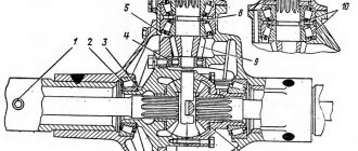
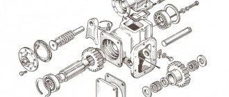
Each element of the propulsion unit, as part of the chassis of a caterpillar tractor, has its own purpose. With a traditional layout, the propulsion unit consists of:
- drive wheel (1);
- caterpillars (2);
- guide wheel (3);
- tensioning and shock-absorbing device (4);
- support rollers (5) and support rollers (6).
The purpose of the drive wheels is to rewind the caterpillar tape while moving and create traction. By location they can be front or rear. In agriculture and forestry, machines with rear drive wheels are used. The main function of this arrangement is to increase efficiency at low speeds up to 25 km/h.
For equipment with a high traction class for industrial use, a propulsion design with highly raised drive wheels is used. Its function is protection from dirt and the use of a modular transmission, which reduces maintenance time. With a modular layout, the shape of the propulsion itself changes from classical to triangular. The front and rear wheels become support wheels, thereby increasing the contact area of the belt on the ground. The purpose of this function is to increase the traction characteristics and cross-country ability of the vehicle.
The crawler tractor propulsion unit is equipped with two caterpillar belts. They perform the task of creating a large supporting surface. The guide wheel, as part of the chassis, performs the following functions:
- ensuring the direction of movement of the caterpillar;
- changes in web tension;
- shock absorption while driving;
- protection of propulsion elements when hit by solid objects.
LLC "Specialized Supply"
Chapter 12 DRIVING BRIDGES
§ 1. Drive axle of a wheeled tractor A drive axle is an axle whose mechanisms transmit torque from the gearbox to the wheels. It includes the housing (crankcase), final drive, differential and axle shafts. Main gear. This is a transmission mechanism that increases torque after the gearbox. It is transmitted at right angles. The drive bevel gear is integral with the shaft or removable. The driven gear is made in the form of a removable ring that is bolted or riveted to the differential housing. To ensure quiet operation, the bevel gears have spiral teeth. While the tractor is moving, the drive shaft, together with the small bevel gear, rotates the driven bevel gear mounted on the differential housing. Differential. It distributes the torque supplied to it between the axle shafts of the drive wheels and promotes their rotation at different speeds.
It consists of a housing 1 (Fig. 77, d), a crosspiece 3, small bevel gears-satellites 4 and semi-axial bevel gears 2. The satellites are freely mounted on the cylindrical fingers of the crosspiece, which, together with the crosspiece, are fixed in the differential housing (box) and are in constant engagement with the gears of the right and left axle shafts. When the tractor moves straight on a flat, dry road, both drive wheels are subject to the same rolling resistance and wheel load. Driven gear 5 (Fig. 77, b) of the main gear rotates the differential housing with the spider and satellites around its axis. The satellites, being in mesh with the right and left side gears, cause them to rotate at the same frequency. In this case, the satellites do not rotate around their own axis.
When turning (Fig. 77, c), the tractor wheels travel different path lengths. The rotation of the inner wheel slows down, and the outer one slows down. The satellites, rotating together with the body, with their teeth rest against the teeth of the semi-axial gear, which has slowed down the rotation, and impart additional speed to the other semi-axial gear. As a result, the outer wheel, covering a longer distance, rotates faster. Rear drive axle of a row crop tractor. Most universal row-crop tractors have one driven rear axle. It consists of final drive, differential, final drives and differential lock mechanism.
The main gear is a pair of bevel gears with spiral teeth.
The drive gear 7 (Fig. 78) of the main gear is made separately and mounted on the KTL secondary shaft. The differential is made detachable, and the crown of the driven gear 5 is screwed to the housing. The housing rotates in two tapered roller bearings. The semi-axial gears are mounted with splined holes on the splines of the shanks of the drive gears 6 of the final drive. The final drives* are located on both sides of the rear axle. Each final drive consists of a pair of spur gears with straight teeth. The drive gear rotates in cylindrical roller bearings. The driven gear is several times larger than the drive gear. The hub of the driven gear has a splined hole with which it is installed on the inner splined end of the axle shaft 9. The oil bath of the rear axle housing is common with the gearbox and the rear compartment of the clutch housing. The rear axle mechanisms are lubricated by splashing oil located in its housing. Oil is poured through the holes in the housing cover to the level of the control hole located on the right wall of the gearbox housing. The differential locking mechanism is necessary to eliminate slipping of one of the driving rear wheels. The differential can sometimes impair the tractor's traction performance. For example, if the traction of one of the wheels is insufficient, it slips, while the other one stands still due to the operation of the differential. To turn it off, it is enough to rigidly connect one of the semi-axial gears to the housing. On the row crop tractor under study, the differential locking mechanism operates automatically. The rear axle differential is locked by a hydraulically driven friction clutch from the power steering. Automatic differential lock (ADL) consists of an actuator mounted on the left brake housing 16 and a sensor (controls the lock) located in the hydraulic booster. The actuator is a clutch. The driving 77 and driven disks of the clutch are connected, respectively, to the splines of the outer end of the shank of the left final drive gear 6 and the grooves of the housing 10 of the locking clutch. A locking shaft 14 is rigidly connected to the clutch body, which passes through the hole of the final drive drive gear and is connected to the differential cross with a splined end. When the ABD is turned off, the clutch discs are released under the action of the springs and the differential operates as usual. When the ABD is turned on and the tractor moves in a straight direction, oil from the power steering is supplied to the cavity between
cover and diaphragm 13. Oil pressure is transmitted through the pressure plate to the clutch friction discs. Due to frictional forces, the disks compressed together combine into one unit the left drive gear 6 of the final drive, the associated left half-axle gear 19 of the differential, the locking shaft 14 and the crosspiece 20. As a result of this, the differential is blocked, since the satellites cannot rotate relative to the left half-axle gears.
On some universal row-crop tractors, the differential locking mechanism is forcibly activated by a pedal. A special gear coupling rigidly connects the axle shafts of the drive wheels. The rear axles of row-crop tractors have a common housing with the gearbox, and the final drives are enclosed in separate housings 2 (Fig. 79, a).
Between the housings of the rear axle and the final drive there is a sleeve 4 axle shafts. The final drive housing is fixed relative to the hose flange with locating pins and bolted. The agricultural clearance is adjusted by changing the position of the final drive and rotating the flange of the front wheel axle axle. Depending on the position of the final drive housing, there are basic and high adjustments. During the main adjustment, the final drive housing is turned back (Fig. 79, b) and its axis of symmetry makes an angle of 7° with the horizontal plane. Front drive axle. It consists of a final drive, differential and final drives. The core of the front axle is a housing, both halves of which are connected by bolts and form a rigid hollow beam. The latter is connected to the semi-frame by a rolling axis. The main gear is a pair of bevel gears with spiral teeth.
Drive gear 1 (Fig. 80), made integral with the shaft, rotates on two tapered roller bearings. They are installed in a glass that is attached to the front axle housing. Between the flange of the cup and the body there are gaskets 2 to adjust the engagement of the main gear gears. Driven gear 3 with an internal ring gear is placed on the gear belt of the differential housing 4 and is pulled through a spacer sleeve by a special nut to the housing ledge. Spacers are installed between the driven gear and the differential housing, which regulate the engagement of the bevel gears of the main drive.
Bevel self-locking differential with floating cross. Housing 4 detachable. It rotates on two tapered roller bearings installed in the front axle housing. Inside the housing (box) there are four satellites, sitting in pairs on two axes placed at right angles. When the front axle is turned on, the axles may move in opposite directions, since they are not secured in the box. Between the satellites and the differential box there are pressure cups 7, connected by splines to semi-axial gears b, manufactured integrally with hollow shanks. In the space between the cups and the box there are locking couplings 5, consisting of steel disks. The driving disks fit into the slots of the box with their protrusions, and the driven disks, using grooves, are located on the splines of the semi-axial gears. When transmitting torque to the front axle while driving in a straight line, if one of the front wheels slips, the satellites begin to rotate on the axles. The axles 8 shift in the grooves of the housing 4, and the force transmitted by the cylindrical surfaces of the satellites through the cup to the friction discs will increase for the lagging axle shaft and decrease for the overtaking one, which eliminates separate wheel slipping. The greater the resistance on the wheels, the more the disks are compressed and the greater the degree of blocking. If the tractor moves without slipping, the front axle is automatically disengaged by the freewheel in the transfer case and the torque from the engine is not transmitted to the differential. In this case, the friction clutch discs are not compressed. The final drive is a wheel reducer, which serves to increase the torque transmitted by the main gear to the front drive wheels and turn them.
The wheel gearbox consists of two pairs of bevel gears: the upper 5 (Fig. 81) and the lower 12. The housings of the 6 upper bevel pairs telescopically fit into the sleeves of the housing 8 of the drive axle, which is important for changing the track of the front wheels. Stepless adjustment of the front wheel track is carried out using a worm mechanism 7. The drive gear of the lower bevel pair rotates on two ball bearings. Due to the movable connection of the drive gear with the vertical shaft, the front axle can be sprung. The driven gear of the lower bevel pair is located on the splined end of the driven shaft 3, to the flange of which the wheel disk 4 is attached. The driven shaft rotates on two tapered roller bearings. Their gap is adjusted by gaskets 2, installed under the flange of the bearing cup.
To lubricate the rubbing parts, transmission oil is used, poured into the housing of the front axle, the upper bevel pair and the wheel gearbox. To prevent oil from leaking out of the housing, self-tightening oil seals and rubber rings are used. § 2. Drive axle of a caterpillar tractor On a caterpillar tractor, the drive axle is usually called the rear axle. It consists of a main gear, planetary gears and final drives.
The rear axle mechanisms are housed in a housing divided by partitions into three compartments. In the middle part there are the main gear and gearboxes of the planetary rotation mechanisms, in the other two there are stopping brakes and sun gear brakes. The final drives are made in separate housings. The final drive includes a pair of bevel gears. The drive (small) gear is manufactured integrally with the gearbox secondary shaft.
The driven (large) gear 4 (Fig. 82) is made in the form of a crown and is bolted to the flange of the ring gear 5. The latter is a drum with teeth cut inside. Between the driven gear and the ring gear flange, steel spacers 3 are installed, which regulate the gap between the teeth of the bevel gears. For ease of removal and installation, the gaskets are made in the form of half rings with open grooves inside for mounting bolts.
Ring gear 5 rests on two ball bearings, pressed with outer races into the bores of this gear. The inner races of the bearings are installed on cups 2. Their flanges are attached to the partitions with bolts. The planetary turning mechanism consists of a planetary gearbox and two brakes: a stopping brake and a sun gear brake. Using the planetary mechanism, you can slow down or stop the transmission of rotation to one of the tracks, and the tractor will turn. The gearbox is mounted inside the ring gear.
It includes
movable body - carrier 17 (Fig. 83, a), three satellites 15 and sun gear 16. The carrier is a steel casting of two triangular flanges connected by cast jumpers. A hub with internal splines is cast to the center of the drive. The splined end of the axle shaft 14 fits into the hub splines. Its other end fits into the internal splines of the drive gear 1 of the final drive. A parking brake pulley 6 is installed on the outer splined shank of the drive gear, which extends into the brake compartment of the rear axle. The satellites rotate freely on needle bearings. Their teeth are in constant mesh with the ring and sun gears; gear 16 is a glass with teeth cut on one end and a flange with threaded holes on the other. The sun gear brake pulley 12 is screwed to the flange. All pulleys are covered by brake bands, which consist of two halves connected by a hinge. With this design of the belts, they can be replaced without removing the brake pulleys. Planetary mechanisms work as follows (Fig. 83, b). When the tractor moves in a straight line, the sun gear pulleys are completely inhibited by the bands, and the axle pulleys are in a free state. Rotation from the main gear is transmitted to the ring gear 18, which sets the satellites 15 in motion. Rotating around the axes, they simultaneously roll around the sun gears 16 (Fig. 83, c), dragging the carrier and the associated axle shafts 14, as well as the drive ones, into rotational motion wheels (sprockets) of the tractor. The rotational speed of the ring gear is reduced by 1.4 times, and the torque increases accordingly. To turn the tractor smoothly, the driver must pull the sun gear brake lever on the side in which the turn is being made. The brake band tension spring is compressed. The belt moves away from the pulley, the sun gear is released and rotates freely with its satellites (Fig. 83, d). The corresponding track is disconnected from transmitting torque and its movement is slowed down due to rolling resistance. The tractor turns smoothly towards the lagging caterpillar. When turning the tractor sharply, after pulling the control lever towards you, additionally press the pedal, braking the parking brake pulley 6 on the side in which the turn is being made. In this case, the movement of the caterpillar stops and the tractor turns sharply towards the stopped caterpillar. All brake bands are steel. Friction linings are riveted to the inner surface of the sun gear brake bands, and a set of pads made of hard friction material is mounted on the stopping brake bands. Each tape in a free state should have the shape of a circle. In a free state, the gap between the pulleys and the belts is 1.5... 1.8 mm. To distribute it evenly, there are tension springs 22 (see Fig. 83, a), as well as adjusting screws 20 screwed into the threaded holes of the rear axle housing. At the upper ends of the brake bands, adjusting screws are fixed, at the ends of which adjusting nuts 2 are screwed. Loops made of strip steel are riveted to the other ends of the bands. The hinges have slots. They include earrings that connect the hinge axes to the fingers of 3 brackets. The fingers are connected through earrings to levers 5 or 7 of the brakes. Lever 5 of the stopping brake is connected by rod 8 to the brake pedal, and lever 7 of the sun gear brake is connected to the control lever. A tension spring 11 rests against one of the arms of lever 7. It tends to turn the sun gear brake levers back counterclockwise (when viewed from the right). The spring force is transmitted through a double-arm lever and earrings to the brake band, which is pressed tightly and with great force against pulley 12.
The gears of the planetary mechanisms and the main gear are lubricated with oil, poured into the central compartment of the rear axle to the top mark on the rod fixed in the filler plug. To prevent oil leakage in the brake compartment, sealing devices are installed in the sun gear hubs. Oil that has penetrated the seal in the brake compartment is removed through threaded holes in the lower part of the housing that are closed with plugs. The control mechanism of a caterpillar tractor includes levers, pedals and rods, with the help of which the tractor is controlled from the cab.
In Fig. 84 shows the levers and pedals for controlling the left and right brakes. Lever 1, through rod 5, acts on the sun gear brake band, and pedal 2, through rod 4, acts on the stopping brake band. Before braking, both fingers 6 of the brake band are in the middle of the cutouts of the bracket 8 and the lever 9 does not have a specific center of rotation. At the beginning of the turn, lever 9 only tightens the ends of the tape. As soon as the brake band touches the pulley, it will move after the pulley and one of the fingers 6 will press against the wall of the bracket cutout. Next, lever 9 will rotate relative to this pin, tightening the tape on the pulley. If the latter rotates in the opposite direction, then lever 9 will rotate relative to the other finger, also tightening the tape. Such pulley brakes, which brake the entire belt in any direction of rotation of the pulley, are called brakes with floating belts. For convenience, the control levers are equipped with plastic handles, and the pedals are equipped with thrust pads. The control levers and pedals are mounted in ceramic bushings on the axles, which fit tightly into the holes of cast iron brackets mounted on the tractor frame. The pedal lever bushings are lubricated through grease nipples screwed into the ends of the axles. Final drives transmit rotation from the rear axle axle shafts to the drive sprockets of the track chains.
The tractor is equipped with two final drives located on both sides of the rear axle.
Each final drive consists of a pair of cylindrical gears enclosed in a separate cast iron housing 1 (Fig. 85). The drive gear 6 rotates on two roller bearings installed in the housing bores. Inside the drive gear there are splines into which the splined end of the axle shaft 10 of the rear axle fits. The crown 7 of the driven gear is made of high-quality steel and is secured with precisely machined bolts to the hub, which is seated on the conical splines of the shaft 3 of the drive sprocket. The sprocket shaft is installed in the housing bores on ball and roller bearings. The drive sprocket 2 is attached to the shaft flange with six bolts. Oil leakage from the final drive is prevented by a self-clamping seal 4. The final drive housing is bolted to the side walls of the rear axle. The housing support 11 is attached using a yoke to the rear axle. The final drives assembled with the rear axle are installed with the middle journals of the supports into the bores of the rear brackets of the tractor frame and secured in them. Thus, the force developed by the drive sprockets during tractor operation is transmitted through the supports to the tractor frame. A steel plate is attached to the upper part of the final drive, protecting the housing from rubbing by the caterpillar. A steel cover 13 is attached to the lower part of the final drive housing, open for mounting the driven gear. It contains holes for
oil level control and drainage, closed with plugs. Oil is poured through the neck located in the upper part of the housing. A breather is mounted in the neck plug. § 3. Maintenance. Possible malfunctions The performance of drive axles is determined by moderate noise and heating, and the absence of oil leaks. For wheeled row-crop tractors, the differential lock must operate reliably and the front drive axle must engage and disengage in a timely manner. Crawler tractors must maintain straight-line motion without acting on the control levers and turn freely when acting on them. The following clearances are adjusted in the main gear. The clearance in the tapered bearings of the drive shaft is adjusted by changing the number of gaskets 3 (see Fig. 78) installed under the flange of the bearing housing. The gap between the teeth of the bevel gears is adjusted by moving shims 18 from one side of the rear axle to the other. For ease of adjustment, the gaskets are split. To release the gaskets, the bearing cups are pressed out using dismantling bolts screwed into the cup flanges. If you move the adjusting shim from the left side to the right, the gap between the teeth of the final drive gears will increase. If you remove adjusting shims of equal thickness from both sides and secure the bearing cups, then, with a constant gap in the meshing of the main gears, the gap in the tapered bearings of the differential will decrease. Normal free play of the control levers of a caterpillar tractor of 80...100 mm corresponds to a gap of 6...8 mm between the rod pins 5 (see Fig. 84) and the sun gear brake lever. This adjustment is made by changing the length of the rods 5. The gap between the band and the stopping brake pulley is adjusted with a nut 7. When the gap is adjusted correctly, the pulley is completely inhibited when the tooth of the right brake pedal is positioned on the first latch, if there are two depressions on the sector, or on the second latch, if there are three . The required gap between the brake bands and pulleys in the lower part is adjusted with screws 20 (see Fig. 83). To do this, in such designs you should know the thread pitch of the adjusting screw. When adjusting the clearances, the locknut is loosened, the screw is screwed in until it stops and unscrewed one turn (if the thread pitch is equal to the required clearance), after which the locknut is tightened. The tightening force of the sun gear brake band, depending on the pre-compression of the springs, is set using the adjusting nut 10 (see Fig. 84). During assembly, it is screwed in so that the groove on the control rod 13 is aligned with the edge of the eye 12-
Oily brake band gaskets are usually washed immediately after stopping the tractor, when they are heated and it is easier to wash off the oil from them. When the brakes are released, the linings are washed with kerosene using a supercharger. After washing, kerosene is washed through the release holes of the compartments into a prepared container and the brakes are left released until the linings are completely dry. As a result of tractor operation, the following malfunctions of the drive axles are possible (Table 9).
Purpose of the rear axle and turning mechanism of crawler tractors
The turning mechanism performs the task of obtaining the translational speeds necessary for turning the tracks. This element is secondarily involved during braking. All this ensures constant stable linear movement of the machine and a smooth transition to curved movement with minimal loss of power.
The turning mechanism of tracked vehicles is dry friction multi-disc clutches and glider mechanisms. They are located behind the rear gear of the tractor. This part receives a flow of power, which is subsequently distributed between the left and right tracks. In some models (T-150), the function of the turning system is performed by a gearbox with hydraulic clutches and brakes.
The rear axle of tracked vehicles ensures the transmission of torque from the engine to the drive wheels, as well as the rotation of the tractor when braking. In addition to friction clutches, the system includes a main bevel gear, band brakes and final gearboxes with drive sprockets.
The peculiarity of this part of the transmission, in comparison with a similar complex of wheeled vehicles, is that it is equipped with a turning mechanism. Its purpose is to change the torques going to the sprockets of the right and left mover (caterpillars). This changes the forward speed of the machine.
The rear axle of a crawler tractor is shown schematically in Fig. 229. Torque from the secondary shaft of the gearbox is transmitted through bevel gears and (central gear) to the shaft of the rotation couplings. Next, the torque is transmitted through the driving and driven parts of the tractor turning friction clutches and cylindrical gears and bevel gears to the drive sprockets of the tractor. When the braking device is turned on, the driven drum of the rotation clutches is braked and the track chain stops faster. These mechanisms are mounted in the rear axle housing and the final drive housing.
The central (main) gear of a caterpillar tractor, as well as the main gear of a wheeled tractor, serves to increase the torque supplied from the gearbox and transmit it through the turning mechanism to the tractor tracks.
In tracked tractors, single-stage central gears are used, consisting of one pair of bevel gears, which are installed in the middle compartment of the rear axle housing 11. The drive gear is usually made in one piece with the secondary shaft of the gearbox, and the driven gear is mounted on the shaft.
The final drives of crawler tractors serve to increase the overall transmission ratio and provide the necessary ground clearance. They consist of cylindrical gears and constant meshing and can be single-stage, like in tractors DT-75M and others, and two-stage, like in tractors T-100M, T-130, etc. The final drives are mounted in two separate crankcases 12, rigidly fixed along sides of the rear axle housing. The parts of the central and final drives are lubricated with oil poured into the crankcases of these gears.
The turning mechanism is used to obtain different translational speeds of the right and left tracks necessary when turning a crawler tractor. At the same time it functions as brakes. The turning mechanism must ensure stable straight-line movement of the tractor and a smooth transition from straight-line to curved movement with minimal power loss.
The tractor turns when the caterpillar towards which the turn needs to be made is disconnected from the transmission. If the disabled track is braked, the tractor turns in place. On tracked tractors, friction steering clutches and a planetary mechanism are used as turning mechanisms.
Friction steering clutches transmit torque from the central gear to the final drive and are multi-plate dry, permanently closed clutches located at the ends of the rear axle drive shaft. Such clutches are used because the torque transmitted by the friction clutch is significantly greater than the torque developed by the engine.
The drive drum (Fig. 230, a) of the coupling is fixed to the splined ends of the central transmission shaft. The driving disks with their teeth are put on the teeth of the driving drum and alternate with driven disks that engage with the teeth of the driven drum mounted on the final drive shaft. The driven discs have linings made of friction material. The drive and driven disks are clamped between the pressure plate and the drive drum flange by springs mounted on studs. A band brake is installed on the driven drum.
When the tractor moves in a straight line, the springs press the disks against each other, and the clutch, being in a closed state, transmits torque from the central gear to the final drive.
Rice. 229. Scheme of the rear axle of a crawler tractor
Rice. 230. Diagram of the friction clutch for turning a caterpillar tractor: a - clutch on: b - clutch off
Rice. 231. Scheme of a single-stage planetary turning mechanism for a caterpillar tractor
To turn the tractor using a lift, the pressure plate moves in the direction of arrow A (Fig. 230, b); the springs further expand and stop transmitting torque to the final drive. At this time, the second clutch remains closed, as a result of which the tractor rotates around the disconnected track. To make sharper turns, it is necessary to additionally slow down the movement of the lagging track by tightening the band brake acting on the driven drum of the disengaged clutch. Friction steering clutches are installed on tractors T-100M, f-74, etc.
Planetary turning mechanisms ensure straight, stable movement of the tractor and provide a more favorable power balance when turning the tractor. Compared to rotation couplings, they are more wear-resistant and smaller in size.
The diagram of a single-stage planetary mechanism is shown in Fig. 231. From the central gear, the torque is transmitted to a box, inside of which there are two cylindrical ring gears, which are in constant engagement with the satellites, which, in turn, are engaged with the sun gears. The satellites are connected to the final drive gears using a carrier. The sun gears are connected to the brake drums. The second pair of brakes is installed on the final drive shafts.
Rice. 232. Diagram of the hydraulic power steering mechanism
When the tractor is moving in a straight line, both sun gear brakes are applied and the brakes are turned off. The planetary mechanism works as a reduction gear.
To turn the tractor, depending on the direction of turn, release the brakes on one of the sun gears and apply the brakes to the final gear. In this case, the torque will be completely transmitted to the running (not disconnected) drive wheel.
A turning mechanism of this type is used on tractors DT-75M and others.
In domestic turning mechanisms of caterpillar tractors, as mentioned earlier, only band brakes are used. In mechanisms with rotation clutches, simple and floating brakes are used, and in planetary mechanisms, only floating brakes are used (see Fig. 228).
The steering clutches and brakes are controlled by a system of rods and levers actuated by the driver from the tractor cab. Typically, the parking brakes are operated by foot pedals that have latches that allow them to be locked in the locked position. The rotation clutches or brakes of planetary mechanisms, which act as a rotation clutch, are driven by hand levers. Each side of the tractor has a separate control system.
To facilitate the control of turning mechanisms (especially in powerful tractors), hydraulic or pneumatic amplifiers are used. When the tractor moves in a straight line, the plunger spool (Fig. 232) closes the oil supply hole in the sleeve to the power hydraulic cylinder of the amplifier. Oil supplied under pressure from the hydraulic pump fills the annular groove on the spool at this time and, not finding an outlet from the sleeve, is drained through the pump safety valve.
When the tractor turns, the driver, acting on the lever, moves the spool, which opens the passage of oil into the discharge channel, while simultaneously closing the drain channel. Under oil pressure, the piston turns the steering wheel through the rod.
After completing the turn, the driver returns the lever to its original position. In this case, the spool, under the action of the spring, will also take its original position, opening a hole in the sleeve to drain oil from the hydraulic cylinder. The return spring moves the piston to its original position, squeezing oil out of the cylinder cavity. The control lever will again be in position for straight-line movement of the tractor.
Thus, the work of controlling the turning mechanism performed by the driver consists of the force applied only to move the amplifier spool.
Purpose and advantage of crawler tractors
The caterpillar tracks provide increased traction with the ground, which increases off-road capability. Using this technique, you can go into the fields immediately after the snow melts or after spring floods, in wetlands. There are other advantages:
- The increased clutch area ensures machine maneuverability and reduces the turning radius, which has a positive effect on fuel consumption.
- A belt-driven tractor provides high efficiency while simultaneously reducing the load on the soil, which prevents soil compaction.
- One of the purposes of machines on tracks is to work with bulldozer equipment due to their high traction performance.
- Due to their good balancing and high load capacity, tractors are used when installing technological equipment.
Friction clutches
Friction clutches , as a rule, are made as multi-plate dry, permanently closed ones. The driving part of the coupling is shaft 1 (Figure a) of the main gear with a drive drum 2 located on its splines. Longitudinal grooves are made on the outer cylindrical surface of the drum, in which thin steel disks 3 are installed with internal teeth.
Drawing. Diagram of the friction clutch: a - the clutch is engaged; b— clutch is turned off; 1 - drive shaft; 2 - driving drum; 3 — drive drum disk with internal teeth; 4 - driven drum; 5 — driven drum disk with external teeth; 6 — drive shaft of the bevel gear; 7 — hairpin; 8 - spring; 9 - pressure plate
The driven part of the coupling is drum 4, mounted on the drive shaft 6 of the final drive. On the inner surface of the drum there are grooves into which the outer teeth of disks 5, equipped with friction linings, enter. The driven and driving disks are assembled through one another. A pressure disk 9 is installed on shaft 1, rotating with the shaft, but having the ability to move along its axis. Pins 7 are screwed into disk 9, passing through the hole in drum 2. Springs 8 are installed on the pins, resting on one side against disk 9, and on the other, against washers mounted on studs 7. Springs compress disks 3 and 5, and the clutch, being in a closed state, creates the required friction torque. In this case, the torque from the main gear is transmitted by clutches to the final drives - the tractor moves in a straight line.
To turn the tractor, you need to disconnect the corresponding caterpillar from the transmission, i.e. disengage one of the rotation clutches. When this clutch is turned off (Figure b), disk 9 moves horizontally, springs 8 are compressed, disks 3 and 5 are released and the rotation of the driven drum and drive sprocket stops. At this time, the other clutch remains closed, as a result of which the tractor rotates around the disconnected track.
Construction machinery and equipment
Rear axle of crawler tractor there are two types.The rear axle with friction clutches and steering control, in addition to the left and right clutches, consists of a main bevel gear, band brakes and two final gearboxes with drive sprockets.
The rear axles of the T-130M and DET-250M tractors are made according to this design. The rear axle housing 14 consists of three isolated compartments. The final gearboxes 2 are attached to the housing on the sides on flanges. The central compartment houses the main gear with bevel gears. It is in the drive axle that increases the transmission ratio and changes the direction of torque by 90°, transmitting it to the drive sprockets, which rotate in a vertical plane. The main gear consists of 8 driving and 7 driven bevel gears. Gear 8 is made integral with the output shaft of the gearbox or is rigidly mounted on it. Gear 7 is rigidly mounted on the drive shaft 9 of the rear axle, which rotates in tapered bearings located in the housing. The bevel gears of the main drive of crawler tractors are characterized by spur gearing. To lubricate the gear pair of the main gear and bearings, an oil bath is provided in the central compartment.
On both sides of the drive shaft, left 5 and right 11 friction clutches are installed, located in the side isolated compartments of the housing 14. These are dry, permanently closed friction clutches, which differ from the clutch clutch in a larger number of disks, due to which they transmit greater torque.
Clutches are called permanently closed, since the clutch disk pack is constantly compressed by pressure springs and the torque is transmitted to the final gearboxes. To disengage the clutches, two levers 6 and 10 are provided at the driver’s workplace, with the help of which the pressure springs are compressed through hydraulic servo control mechanisms, the disks are opened and the transmission of torque to one of the drive sprockets is stopped. The outer drums of the friction clutches are used to accommodate band brakes 3 and 13 of the tractor. They are controlled using pedals 4 and 12. The side compartments of the bridge housing, in which the friction clutches and band brakes operate, are reliably protected by seals from the penetration of oil from the central compartment and the final gear housings. The clutch drums are rigidly mounted on the input shafts of two-stage final gearboxes 2. The final gearboxes increase the torque to the calculated value and transmit it to the drive sprockets 1.
The operating principle of the bridge is as follows. When the friction clutches are turned on and the brakes are off, the torque is uniformly transmitted to sprockets 1. They are rigidly connected to each other by the bridge mechanisms and have the same angular velocity. The tractor moves straight and evenly.
When the left friction clutch is turned off, the transmission of rotation to the left sprocket stops and the right track overtakes the left. As a result, the entire car turns to the left with a certain radius. When the left brake is activated, the movement of the left track stops and the tractor turns sharply relative to the braked track. If it is necessary to turn the tractor to the right, disengage the right clutch accordingly and apply the right brake. Turns in motion and in place are carried out equally in forward and reverse gear.
Rice. 29. Schemes of rear axles of caterpillar tractors:
a - with friction clutches for steering control, 6 - with a planetary steering control mechanism; 1 - sprockets, 2 - final gearboxes, 3, 13, 16, 23 - brakes, 4, 12 - left and right pedals, 5, 11 - control clutches, 6,' 10 - control levers for the left and right clutches, 7. 8 , 19 - gears, 9, 78-shafts 14 - rear axle housing, 15 - pulleys, 17 - drum with rings, 20 - drive, 21 - ring 22 - satellite.
The tractor is braked by turning on two (during operation) or one (while parking) band brakes and disengaging the friction clutches of the rear axle or clutch.
The rear axle with planetary steering control mechanisms (planetary gearboxes) is shown . The main advantage of this axle is that planetary gearboxes perform not only the functions of steering control mechanisms, but also allow increasing engine torque. This reduces the number of steps and simplifies the design of the final drives, as well. the durability of the turning mechanisms is increased. Crawler tractors such as DT-75 and T-180G are equipped with such bridges.
Gear 8 of the main gear meshes with gear 7, which is rigidly fixed externally to drum 17. The drum rotates freely in the central compartment of the housing. On the inside, the drum is equipped with two symmetrical crowns of 21 ring gears with internal gearing. Three satellites 22 are engaged with each ring gear. The satellites are connected to carriers 20, which are rigidly connected through a shaft to the drive gear of the corresponding final gearbox. Brake pulleys 15 for the left 3 and right 13 side brakes of the tractor are installed on the shafts.
At the same time, the satellites engage with the sun (central) gear 19, which is connected by a hollow shaft to the pulley of the permanently closed brakes 16 and 23 of the planetary gearboxes. The brakes of the planetary gearboxes are constantly closed and are turned off by levers 6 and 10 from the driver’s seat. The tractor brakes are controlled using pedals 4 and 12.
A bridge with planetary mechanisms works as follows. Gear 8 drives gear 7, which rotates together with drum 17 and internal rims. Due to the fact that brakes 16 and 23 are constantly braked, the sun gears are stopped. The satellites, driven by gears 21, roll around the fixed gears 19 and cause the carrier 20 to rotate at a certain frequency. They transmit torque to the right final gearboxes and the drive sprockets of the tracks,
Since the left and right planetary gears are the same in design and number of teeth in the gears, and the final gearboxes are unified, sprockets 1 rotate at the same frequency and the tractor moves in a straight line. When one of the brakes of the planetary mechanism is released, gear 19 rotates freely with the carrier stopped from the ring gear with the help of satellites. The transmission of rotation to the final gearbox and gear 8 stops, and the tractor begins to rotate around the disconnected track. When the appropriate brake (3 or 13) is applied, the track is braked and a sharp turn around a stationary track is possible.
Thus, when the right brake of the planetary mechanism is released and the right side brake is applied, the tractor turns to the right accordingly. The effect of the brakes is the same when the tractor is moving forward and in reverse. The machine slows down when brakes 16 and 23 or the tractor clutch are turned off and brakes 3 or 13 are turned on.
The design of the rear axle with planetary turning mechanisms of a DT-75 type tractor is shown.
The bridge body 31 consists of three compartments: a central one and two side ones. Each compartment is separated by solid partitions. The central compartment contains the main gear and planetary turning mechanisms, the side compartments contain the brakes of the planetary gearboxes and the onboard stopping brakes of the tractor. The main gear consists of a pair of bevel spur gears. The drive gear (not shown in the figure) is made integral with the output shaft of the gearbox (see § 6). The driven gear 26 is bolted to the flange of the ring gear drum of the planetary mechanisms. Between the gear and the flange there is a package of steel gaskets 27, with the help of which you can also adjust the gap in the bevel gear of the main gear pair. The gaskets are made in the form of half rings with open grooves for mounting bolts. Therefore, the gaskets are removed and installed when the bolts are loosened.
The ring gear drum rotates on two ball bearings. The inner rings of the bearings are mounted on cups 11, the flanges of which are bolted to the internal transverse partitions of the housing.
Two identical planetary mechanisms are mounted inside the drum on 24 ring gears with internal involute teeth.
Meshing with the ring gears includes two parallel rows of spur gears 23. Each row of satellites is installed in cast carrier housings 25. Three satellites are installed evenly around the circumference in the row. They rotate on needle bearings and axles rigidly pressed into carrier housings. At the same time, the satellites of each row are in mesh with the sun gears of 21 planetary mechanisms. The gears 21 are connected by hollow shafts to the left 16 and right 19 brake pulleys. The hollow shafts rotate in sliding bearings pressed into cups 11. The housings of the carrier shafts are connected to the left 1 and right 15 drive gears of the final gearboxes. The gears 15 of the gearboxes are connected by hollow shafts to the pulleys 16 of the side brakes 17. The planetary mechanisms and the tractor are affected by belt-type brakes. Each band brake of planetary mechanisms is made of a steel band with riveted fabric asbestos linings and is constantly tightened by a cylindrical spring 9. Thanks to the use of planetary mechanisms, the torque increases by 1.42 times. Each brake 17 is equipped with a steel band with hard friction pads and is permanently open.
To set a certain tightening force for the brake band, adjusting nuts 32 and 33 are provided for the planetary gears and onboard brakes, respectively. To reduce wear on the brake bands, all brakes are equipped with upper 8 and lower 18 release springs, which create a gap between the bands and the brake pulleys when the brakes are turned off. The brakes are controlled using lever mechanisms. The brakes of planetary mechanisms are operated by two levers, and the onboard brakes are operated by pedals located at the driver’s workplace.
No oil should get into the side sections where the brakes operate. The shafts are sealed with oil seals. To remove possible accumulations of liquid and oil, drain plugs 29 are installed in each compartment.
Oil is poured into the central compartment to lubricate the main gear engagement, planetary mechanisms and bearings. A plug with an oil meter is screwed into the filler neck, on which oil level marks are applied. To drain the oil, a drain plug with a magnetic catcher for metal wear products is screwed into the bottom of the compartment.
The tractor is braked during operation by turning on two side brakes; when parked, by turning on and placing the right brake pedal on the lock. The engagement of a pair of bevel gears of the main gear is adjusted after removing the cover 5 of the central compartment. Using spacers 23, install the small gear in the axial direction in such a position that the size from its end to the axis of the rear axle is 133 (+ 0.3) mm. The thickness of each spacer is 0.15 mm. Then, using spacers 27 between the large gear 26 and the ring gear drum flange, the lateral clearance between the main gear gears is set to 0.25...0.51 mm. The clearance is checked using an indicator or a lead plate every 90° when the large gear is fully rotated. After this, the bevel pair of the main gear is run in and the teeth run-in marks are checked. Allowed are prints that make up 60% of the length of the teeth and are spaced no more than 6 mm from the base of the teeth. Prints are possible in the form of individual spots 10 mm long with a gap between them of no more than 8 mm. After this, the lateral clearance in the engagement is checked again.
Then tighten all the bolts, lock them and close the hatch.
The brakes are controlled by devices located in the rear wall of the axle. The regulation sequence is given in § 11 and 12.
Rice. 30. Rear axle with planetary control of a tractor type DT-75:
1,15,21,24,26 - gears, 2 - control box, 3 - brake control lever rods, 4 - cover, 5,10 - covers, 6,14 - shafts, 7 - roller bearing, 8,9,18 - springs, 11, 12 — cups, 13 — oil seal housing, 14 — rear axle shaft, 16, 19 — pulleys, 17, 20, 30 — brakes, 22 — satellite pin, 23 — satellites, 25 — carrier, 27 — gasket, 28—ball bearing, 29—plug, 31—housing, 32,33—nuts.
See also:
9.2. TRANSMISSION OF BULLDOZERS AND TRACTORS T10M T-170
9.2.1 . Hydromechanical transmission
A hydromechanical transmission consists of a torque converter and a planetary gearbox connected to each other by a driveshaft, a main gear, final clutches, brakes, final drives and a transmission control and lubrication system.
The torque converter (Fig. 9.16) is designed for stepless automatic change of torque and output shaft speed depending on the magnitude of the external load, as well as damping torque fluctuations (torsional vibrations from the diesel engine are not transmitted to the transmission, loads passing through the chassis and transmission, are not transferred to diesel).
The torque converter consists of impellers: pump, turbine and reactor, installed relative to each other with small gaps. The interblade cavities of the wheels form a torus in which the working fluid circulates. In the pump wheel connected to the diesel engine, the mechanical energy of the diesel engine is converted into kinetic and potential energy of the liquid; in the turbine wheel (connected to the output shaft) it is again converted into mechanical energy.
| A-A | |
| Rice. 9.16. Torque converter; 1 – torque converter casing; 2 – cardan coupling half; 3 – diesel flywheel; 4. – diesel flywheel casing; 5 – turbine wheel; 6 – breather; 7 – pump wheel; 8 – reactor wheel; 9 – sealing rings; 10 – working fluid inlet; 11 – outlet of working fluid; 12 – pumping pump NMSh-25; 13 – gear wheel of the pump drive; 14 – intake; 15 – reactor axis; 16 – turbine shaft; 17 – pump NSh-50A-2; 18 – gear wheel of the NSh-50A-2 pump drive; 19 – magnetic filter; 20 – fine filter; 21 – temperature indicator sensor TM100-V; 22 – emergency pressure sensor MM126D; 23 – valve for exiting the GTR; 24 – emergency pressure sensor MM129 | |
In the reactor, the direction changes and the flow speed decreases, and the torque is transformed by an amount perceived by the reactor. The torque converter impeller supports are located on the hub and output shaft.
The working fluid in the torque converter torus is under excess pressure. The torus seal is ensured by two pairs of fluoroplastic sealing rings.
A drive gear is attached to the pump wheel (Fig. 9.17), which is in mesh with the drive gear of the NMSh-25 pump-out pump, and it in turn is in gear with the drive gear of the NSh-50A-3 pump of the control and lubrication system. Lubrication of the pump drive is provided by oil coming from the outlet channel of the torque converter torus through tube 22 (Fig. 9.23), channels in the torque converter housing and bearing housings.
| Rice. 9.17. Pump drive: 1 – gear wheel of the NSh-50A-3 pump drive; 2 – gear wheel of the drive of the pump-out pump NMSh-25; 3 – pump wheel; 4 – gear drive wheel; 5 – casing; 6, 12 – bearing housings; 7, 9 – spacer; 8 – hairpin; 10, 11 – coupling |
The following are installed on the torque converter casing: breather, valve for exiting the turbocharger (Fig. 9.18)
Rice. 9.18. GTR outlet valve:
1 – cover; 2, 6 – body; 3 – spool; 4 – spring; 5 – ring; 7 – washer; 8 – seal
and filter (Fig. 9.19).
| The internal cavity of the filter is divided into two chambers. At the bottom, connected to the suction line, there is a magnetic filter, at the top, connected to the discharge, there is a fine filter. The magnetic filter ensures the cleaning of the working fluid from iron particles. It consists of permanent magnets arranged with like poles facing each other. The fine filter consists of filter elements installed on a pipe. The cavities of crude and purified oil are separated by a lid 7 (Fig. 9.19). A valve 11 is installed on the cover, which is activated when the filter elements are contaminated to a state that prevents the passage of the entire oil flow. Working with this valve in the open position is allowed only if it is necessary to move the tractor to a repair base and it is impossible to clean the filter elements on site. The fine filter is connected through a pipe with a magnetic filter into a single block, which can be removed during maintenance along with cover 7. The cover has two threaded holes for a puller. In case of replacing filter elements, ensure dimension A (52 ± 3 mm) (Fig. 9.19) by installing the required number of filter elements (72 max). The seal between the cavity of the fine filter (high pressure - discharge of the NSh-50 pump) and the cavity of the magnetic filter (low pressure - suction of the NSh-50 pump) is ensured due to the tight fit of the end-pipe 13 to the end of the lower housing 3 of the filter. | Rice. 9.19. Filter: 1, 13 – pipe; 2 – magnetic filter; 3 – lower filter housing; 4 – upper filter housing; 5 – spring; 6 – fine filter; 7, 9 – cover; 8 – fitting; 10 – emergency pressure sensor MM129; 11 – valve; 12, 14 – coupling; A-52±3mm |
The cardan shaft (Fig. 9.20) is double-jointed.
The spikes of the cardan crosses are pumped on needle bearings. The ends of the propeller shaft are connected to the coupling half of the output shaft of the torque converter and to the coupling half of the drive shaft of the planetary gearbox. For swamp tractors, the length of the cardan shaft is increased by 350 mm. The flange is replaced with a pipe.
| Rice. 9.20. Cardan: 1 – flange; 2 – cross; 3 – support; 4 – valve; 5– bolt; 6 – bearing; 7 – cover |
The gearbox is reversible planetary (Fig. 9.21), three-speed with gear shifting on the fly. The planetary part of the box consists of five elementary planetary gears, five friction disc brakes operating in oil, which are activated by hydraulic boosters.
Rice. 9.21. Planetary gearbox:
1 – gearbox housing; 2, 14 – carrier; 3 – shaft; clutches: 4 – forward, 5 – reverse, 6 – second gear, 7 – third gear, 8 – first gear; 9 – spacer; 10 – pipe; 11 – fitting; 12 – ring; 13 – gear shaft; 15 – satellite bearings; 16 – housing of the matching gearbox
Planetary gears are made according to the diagram (Fig. 9.22).
Rice. 9.22. Planetary gear diagram:
A – diagram of 1, 3, 5 planetary gears; B – diagram 2, 4 planetary gears
1 – epicycle; 2 – sun gear; 3 – satellite
The first two planetary gears serve as a reverse mechanism. When the 1st clutch , forward movement , and when the 2nd clutch is closed, reverse movement .
Three subsequent planetary gears serve as a gearbox. When the 3rd clutch the second gear , the 4th clutch is engaged in the third gear , and the 5th clutch is engaged in the first gear .
The drive shaft is mounted on rolling bearings installed in the gearbox housing. The rear splined end of the shaft is used for power take-off. The sun gears of the reverse mechanism are installed on the shaft splines, the first carrier is mounted on ball and roller bearings, in which the satellites of the 1st, 2nd and 3rd planetary gears are installed on axles on needle bearings without cages. The satellites of the 4th and 5th planetary gears are mounted on the axes of the second carrier, which is fixed in the gearbox housing using a ball bearing.
On the outer surfaces of the epicycles, slots are cut into which discs with copper-based cermets are installed. Smooth discs are connected to hydraulic friction brake housings. With the help of hydraulic equipment, the fluid enters under the piston of one of the brakes, which, moving, closes the package of friction discs, thereby stopping the epicycle of the planetary gear set. When the tractor is moving, two brakes are applied: the reverse mechanism (forward or reverse) and the gearbox (first, second and third gears). When the gear shift lever is in neutral, the brake of the 3rd planetary gear set is engaged, which ensures that the planetary gear sets are centered relative to the housing.
An alignment reducer is installed behind the planetary part of the gearbox, providing the required center-to-center distance between the power take-off shaft and the output shaft of the gearbox.
The drive gear is connected to the sun gear of the third and fifth planetary gears. The driven gear is connected to the output shaft, which ends in the small bevel gear of the main drive.
Gear changes are carried out without interrupting the power flow.
From the drive shaft, through planetary mechanisms and a matching gearbox, power is transmitted to the main gear shaft. Shifting gears and reverse is ensured by control lever 13 (Fig. 3.5), 1 (Fig. 8.16).
To change gears, the movement of the lever is transmitted through the gear shift controls (Fig. 8.14, 8.15) to the spool of gear block 13 (Fig. 8.14).
The spool of the gearbox is secured by a locking lever 6.
A diesel start blocking switch VK415 is installed on top of the gearbox cover opposite the gearshift control rod. In the neutral position of the gearshift lever, the switch is open. When 1st gear is engaged, it is closed.
To switch reverse, the movement of lever 1 (Fig. 8.16) is transmitted through the lever control system for switching reverse (Fig. 8.15, 8.16) to the spool of reverse block 7 (Fig. 8.14).
Fixation of the reverse block spool is ensured by a locking lever 15.
On top of the gearbox cover, opposite the reverse control rod, there is a switch VK415 for an intermittent sound signal, which closes when the control lever is moved to the reverse position (REV).
ATTENTION! The alarm system operates continuously when the tractor moves backward.
When forward is engaged, the switch is open.
You can check the operation of the start interlock switches and the intermittent sound signal under a voltage of no more than (24 ± 2) V and a current of no more than 1 A.
The hydraulic equipment of the control and lubrication system (Fig. 9.23, 9.24) is mounted on the torque converter housings and the friction brake housings of the planetary gearbox.
The control system provides:
– filling the torque converter torus with working fluid under excess pressure;
– fluid supply to the reverse and gear shift friction brakes;
– lubrication of torque converter and gearbox bearings;
– smooth activation of transmission clutches;
– setting the gearbox control lever to the neutral position when the diesel engine stops or the pressure in the control system drops.
Four hydraulic units are mounted on the friction brake housings of the planetary part of the gearbox:
– a gear unit with a four-position spool for supplying working fluid to the reverse friction brakes;
– a reverse block with a two-position spool for supplying working fluid to the reverse friction brakes;
– a plate with a blocking safety valve spool 16 (Fig. 9.24) and a valve for regulating the pressure of the working fluid at the inlet to the torque converter in the range from 0.48 to 0.51 MPa (from 4.8 to 5.1 kgf/cm²);
– the valve block, which ensures smooth starting of the tractor, consists of two valve systems: bypass valve 8 (Fig. 9.24) and pressure valve 28, adjusted to a pressure of 2.2 to 2.5 MPa (22 to 25 kgf/cm² ), designed to limit the maximum pressure and ensure that the gear and reverse clutches are engaged in a certain sequence.
An outlet valve from the GTR is installed on the GTR body, providing pressure at the outlet of the torque converter in the range from 0.22 to 0.28 MPa (from 2.2 to 2.8 kgf/cm²).
When the diesel engine is running, working fluid from the gearbox pan flows through sleeve 23
(Fig. 9.23) into the lower internal cavity of the GTR filter housing, where the magnetic filter is located.
Rice. 9.23. Hydraulic power supply, control and lubrication system of the GMT:
1 – radiator; 2 – magnetic filter; 3 – fine filter; 4 – emergency pressure sensor MM129; 5 – temperature indicator sensor TM100-V; 6 – emergency pressure sensor MM126-D; 7 – valve for exiting the GTR; 8 – torque converter; 9 – pump NMSh-25 (pumping); 10 – oil supply pipe to the GTR; 11 – reverse block; 12 – valve block; 13 – gear block; 14 – high pressure hose; 15 – emergency pressure sensor MM111-B; 16 - filter; 17 – gearbox lubrication valve; 18 – planetary gearbox; 19 – GTR pan; 20 – pump NSh-50A-3; 21 – GTR filter pipe; 22 – pump drive lubrication tube; 23 – sleeve
After the magnetic filter, the working fluid enters the suction cavity of the NSh-50A-3 pump, after which it enters the upper internal cavity of the filter, where the fine filter is located.
After fine cleaning, the working fluid through the high-pressure hose 14 enters the gearbox transmission unit, from where, depending on the position of the spool, when the gear is engaged or in neutral, it enters under the piston of one of the brakes.
Rice. 9.24. Diagram of the hydraulic power supply system for GMT control and lubrication,
neutral position (with diesel engine running):
1 – gearbox tray; 2 – magnetic filter; 3 – valve block; 4 – plunger; 5 — pump NSh-50A-3; 6 – check valve; 7 – fine filter; 8 – bypass valve; 9 – safety valve for inlet to the GTR; 10 – emergency pressure sensor MM129 of the gearbox control system; 11 – gear block; 12 – spool of the gearbox; 13 – safety valve spool; 14 – spool valve of the reverse block; 15 – reverse block;
16 – safety valve; 17 – oil distribution plate;
18 – emergency pressure sensor MM111-B of the gearbox lubrication system;
19 – gearbox lubrication valve; 20 – oil radiator; 21 – gearbox lubrication system filter; 22 – torque converter; 23 – valve for exiting the GTR; 24 – emergency pressure sensor MM126-D at the outlet of the gas turbine unit; 25 – temperature indicator sensor TM100-V of the torque converter; 26 – GTR pan; 27 – pump-out pump NMSh-25; 28 – pressure valve