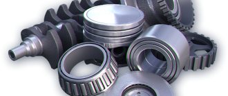
8.2. Checking the oil level in the gearbox and rear axle
Checking the oil level must be done with the vehicle unloaded, placed on a level surface, and with the units cooled down.
The oil level in the gearbox should be level with the lower edge of the filler hole - fig. 8.1.
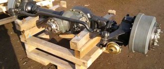
The oil level in the rear axle (Fig. 8.2) should be at the level of the lower edge of the filler hole.
Rice. 8.1. Checking the oil level in the gearbox:
1 — drain plug;
2 - filler plug
Rice. 8.2, Checking the oil level on the rear axle:
1 — drain plug;
2 - filler plug
8.3. Checking the coolant level
Check the coolant level in expansion tank 2 (Fig. 8.3) only on a cold engine.
The fluid level in the expansion tank should be at the “MIN” mark or 30–50 mm above it.
Rice. 8.3. Checking the coolant level in the expansion tank:
1—cork; 2 - tank
Add coolant through the opening of the expansion tank, which is closed with a plug. When frequently adding fluid, it is necessary to check the tightness of the cooling system.
8.4. Checking the electrolyte level in the battery
The electrolyte level in the battery should be between the MIN and MAX marks (Fig. 8.4) marked on the translucent battery body, and if they are absent, along the lower edge of the filler hole.
If the electrolyte level is below normal, it is necessary to remove cover 1, unscrew plugs 2 and through holes 3 add distilled water to the battery cells to the normal level; then tighten the plugs 2, having first checked the cleanliness of the ventilation holes in them and install the cover 1. After this, you need to wipe the outer surfaces of the battery with a clean rag soaked in a 10% solution of ammonia or baking soda.
Rice. 8.4. Accumulator battery:
1 - cover; 2 - plug; 3 - filler hole
It is necessary to constantly monitor the cleanliness of the battery terminals and wire clamps, as well as the reliability of their connections.
When installing the battery on a car, you must ensure that the wires are connected in accordance with the polarity indicated on their tips and battery terminals (positive terminal is greater than negative).
Before installation on the car, the batteries are charged to a density of 1.25-1.27 g/cm3. Depending on the climatic region in which the vehicle is used, the electrolyte density must be adjusted (see the battery operating instructions).
When parking the car for a long time, disconnect the battery from the car body to ensure fire safety.
Battery switch (installed on vehicle parts). To disconnect the battery during long-term parking or when repairing electrical equipment, a battery switch 12 (see Fig. 5.1) is installed to the right of the driver’s seat.
To avoid failure of some electrical equipment, it is not allowed to disconnect the battery while the engine is running.
8.6. Tension of accessory drive belts
8.6.1. Engine D-245.7 E3
The tension of the fan belt is checked by pressing on the middle of the branch between the crankshaft and generator pulleys with a force of 4.0 daN (4.0 kgf), while the deflection should be in the range of 12–17 mm. To adjust the belt tension, you need to loosen the generator, turn it and tighten the belt.
Tighten the bolt securing the bracket and the nuts of the generator mounting bolts. The belt tension is considered normal if its deflection on the crankshaft pulley - generator pulley branch (Fig. 8.6) is within 12–17 mm when pressed with a force of 4.0 daN (4.0 kgf).
Rice. 8.6. Checking the fan belt tension
8.6.2. Engine ZMZ-5231
Belt tension is checked using a spring dynamometer. The belt is tensioned correctly if, under a load of 4.0 daN (4.0 kgf) in the middle of the section between the generator and fan pulleys, the deflection is within 10–15 mm.
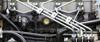
Fuel system of the Gazelle Cummins ISF 2.8 engine
______________________________________________________________________________
The Cummins ISF 2.8 diesel engine of the Gazelle Business uses a fuel system with a common high-pressure fuel line and an electronic control system. The high pressure fuel line system consists of 4 main elements: the gear fuel pump, the high pressure pump, the common high pressure fuel line and the injectors. The high pressure pump supplies fuel to the common high pressure fuel line regardless of engine speed. Fuel under high pressure accumulates in this fuel line, from where it is constantly supplied to the injectors. The ECM regulates fuel supply and injection timing by turning on the injectors. A water separating fuel filter must be installed on the fuel intake side. It is located outside the engine and contains a manual booster pump.
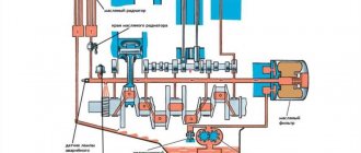
Fig.6. Cummins ISF 2.8 diesel fuel system diagram
1 - Fuel supply from the tank, 2 - Fuel filter, 3 - Fuel water separator drain pipe, 4 - Booster pump, 5 - Fuel supply to the fuel pump, 6 - High pressure fuel pump, 7 - Fuel supply to the common high pressure fuel line, 8 — Common high pressure fuel line, 9 — Fuel supply to the injectors, 10 — Injector, 11 — Drain fuel from the injectors, 12 — High pressure reducing valve, 13 — Drain pipe of the high pressure reducing valve, 14 — Drain fuel line, 15 — Drain fuel into tank The gear fuel pump of the Cummins ISF 2.8 diesel engine of the Gazelle Business car creates a pressure of about 303 - 1303 kPa, due to which the fuel is cleaned in a filter installed on or outside the engine before entering the injection pump. In this pump, the fuel pressure increases to a level of 250 - 1600 bar in three radial discharge chambers. The electronic fuel control system actuator valve, installed at the inlet to these chambers, regulates the amount of fuel entering them. To do this, it uses signals from the ECM, which maintains the pressure in the common high-pressure fuel line at the required level. Fuel that does not enter the plenums exits through the cascade bypass valve. It directs part of the fuel under pressure into the lubrication system channels of the Cummins ISF 2.8 diesel high-pressure pump and then drains the fuel into a tank, which accumulates fuel and distributes it between the fuel lines of individual injectors. It contains a sensor that monitors the pressure created in it by the high-pressure pump. The signal from this sensor is used by the ECM to control the flow of the high pressure fuel pump. In addition, there is a pressure reducing valve in the common fuel line. It works as a safety valve, releasing excess pressure if the pressure in the fuel line exceeds a set level. Fuel drained from the common high pressure fuel line is returned to the fuel tank through the fuel return line.
High pressure fuel pump injection pump Cummins ISF 2.8
Work on checking and dismantling the injection pump Cummins ISF 2.8 Gazelle Business:
— Clean all fittings before disassembly. Dirt may cause damage to the fuel system. — Turn the starting switch to the ON position and turn on the starter to check the operation of the high pressure fuel pump. — Disconnect the fuel line going to the common high pressure fuel line from the Cummins ISF 2.8 injection pump. — Connect a clean hose to the outlet of the high pressure fuel pump. — Insert the other end of this hose into an empty container. — Turn on the starter for 30 seconds and measure the flow of the fuel pump.
— The fuel pump flow must be at least 45 ml in 30 seconds at 125 rpm or 53 ml in 30 seconds at 150 rpm.
If the supply of the Cummins ISF 2.8 injection pump during starter operation does not meet the minimum standard, do the following: — Check for the absence of air in the fuel. — Check for blockages in the fuel inlet line. — If these tests are normal, check the resistance of the electronic fuel control system control valve. — After replacing the electronic fuel control system control valve, re-measure the fuel pump flow. — If the minimum fuel supply is not normal, replace the pump. — Connect the electrical connector of the Gazelle Kamens injection pump control valve and clear all fault codes using the diagnostic kit. — If the engine does not start, measure the fuel flow through the fuel return line - this will help identify a malfunction of the high pressure fuel pump. — A faulty return line bypass valve or fuel pump can cause high fuel flow through the fuel return line. — Be sure to measure the fuel consumption through the fuel drain line while the Kamens 2.8 diesel engine is idling. — The fuel system leak test provided in the diagnostic kit can be used to increase the pressure in the fuel system, allowing a larger leak to be identified. — Remove the fuel drain quick connect fitting from the high pressure pump. — To reduce the risk of fuel leakage from the combined high pressure fuel and injector return line, seal the flexible fuel return line with a fuel line plug. — Place the drain hose with quick-release fitting onto the fuel injection pump drain pipe. Place the end of the fuel drain hose into the graduated cylinder. — Start the Cummins ISF 2.8 diesel engine of the Gazelle Business car and bring it to idle speed. — When fuel begins to flow into the graduated cylinder, measure the flow rate for 30 seconds. — The maximum flow rate for 30 seconds at nominal idle speed (800 rpm) is 310. — If the high-pressure injection pump does not meet fuel supply standards, check the presence of air in the fuel and the resistance at the fuel inlet. — If the results of these tests are normal, the fuel pump must be replaced. — Clean all fittings before disassembly. Dirt may cause damage to the fuel system. — Disconnect the batteries. Disconnect and remove the fuel supply and drain lines.
— Disconnect the fuel supply line (1) leading to the high pressure common fuel line from the high pressure fuel pump and loosen the support brackets (2). — Disconnect the electronic fuel control system control valve (3) wiring harness connector. — Remove the three flange bolts securing the injection pump. — Remove the fuel pump from the timing gear housing.
Dismantling and assembling fuel injection pump of diesel engine Kamens 2.8
— Using a gear replacement tool, hold the fuel pump drive gear in place. — Loosen the nut securing the injection pump drive gear of the Cummins ISF 2.8 diesel engine by turning it counterclockwise. Do not remove it from the shaft. — Install a bearing remover between the pump mounting flange and the drive gear. — Lock the bearing remover. — Place the puller on the bearing remover and the pump drive shaft. — Rotate the puller screw until the gear is separated from the drive shaft. — Remove the fuel pump drive gear nut, lock washer and the gear itself from the fuel pump drive shaft. — Check the drive shaft and gear for damage. Replace damaged parts. — Check the O-ring for damage. Replace the O-ring if damage is found. — Check the installation location of the O-ring for damage. Clean and restore all damaged surfaces. — Check the timing gear housing, the hole for the fuel injection pump of the Cummins ISF 2.8 diesel engine and the mounting studs for cracks. — Replace any damaged parts. — Before assembly, clean and dry the toe of the drive shaft and the seating surface of the drive gear. — Wipe the drive shaft and gear with a lint-free cloth moistened with solvent. Do not touch the seating surfaces after wiping. — Mount the drive gear on the drive shaft. — Install the lock washer and pinion nut and tighten the nut by hand. — Using a fuel pump gear replacement tool and a 1.25 mm pry bar, hold the fuel pump drive gear in place while tightening the drive nut.
Installation of fuel injection pump Kamens 2.8 for Gazelle Business cars
— Install the fuel pump onto the timing gear housing. — Insert and tighten the Cummins ISF 2.8 injection pump mounting bolts. — Install the fuel supply line leading to the high pressure common fuel line from the high pressure fuel pump and tighten the support brackets. — Connect the electronic fuel control control valve harness connector. — To avoid sparking, disconnect the negative (-) battery cable first and connect it last. — Connect and install fuel supply lines. — Connect and install fuel drain lines. — Connect the electronic fuel control control valve harness connector. — Connect the batteries. Fill the fuel system.
Cummins ISF 2.8 injector
Work on dismantling the Kamens 2.8 injector:
— Remove the injector holder bolt. — To reduce the risk of damage to the valve cover seal mandrel, continue turning the bolt counterclockwise as the bolt threads begin to pass through the valve cover seal mandrel. Remove the injector holder clamp. — To remove the nozzle, lightly move the nozzle and turn the nozzle by hand, carefully swinging it in different directions. — If additional force is required to remove the Cummins ISF 2.8 diesel injector, use a special tool. — Carefully insert the tool into the recess of the rocker arm cover. — At the same time, make sure that the two supports of the device are securely located under the nozzle collar. —Using the impact slider, apply a smooth vertical force to the body toward the T-handle. — Do not use devices with a magnetic coupling, magnetic pull or electrical connector. — Place the protective cap on the injector nozzle. Remove the protective cap from the nozzle nozzle. — Lower the Cummins ISF 2.8 Gazelle Business nozzle vertically into the ultrasonic bath. — Connectors of high pressure fuel lines and electrical connectors must be protected from contact with detergent. — You can also use a clean, thin, lint-free cloth to remove dirt deposits. — During cleaning, do not remove the protective caps from the fuel inlet and drain lines. — Check the nozzle tip for carbon deposits or corrosion. — Cover the nozzle nozzle with a protective cap and store the nozzle in a clean place until installation. — Check the electrical connector for damage. — The resistance at the contacts should be in the range of 0.215 - 0.295 Ohms.
Operations for installing a Cummins ISF 2.8 diesel injector:
— Write down the injector setting code and the installation location of each injector. — The injector setting code is a seven-digit alphanumeric code printed on the top of the injector. — Before installation, apply anti-seize compound or its equivalent to those parts of the injector where it touches the cylinder head. — When installing injectors, use a copper sealing washer. — Check that the thickness of the injector sealing washer is correct. — The thickness of the sealing washer of the Cummins ISF 2.8 injector is 1.5 mm. — Only one copper sealing washer should be installed per nozzle. — When installing the injector, be careful not to damage the injector tip. — Remove dirt from around the valve cover and remove the plug installed to prevent dust and debris from entering the engine. — The valve cover seal should be lightly lubricated to facilitate installation of the injectors. — If the nozzle is not damaged, install it in its original position during reassembly. — Use the vertical clamp as a guide to carefully insert the injector into the cylinder head through the valve cover and align the fuel line fitting with the common high pressure fuel line. — Loose tightening of the fuel supply line when connecting it to the Kamens 2.8 injector will facilitate its accurate installation. — Install the bolt to secure the clamp and tighten the bolt. — Visually compare the height of the injectors to ensure there are no missing or extra copper O-rings. — Install high pressure fuel lines. Install fuel drain lines. — Insert the electrical plugs. They should make a characteristic sound when fixed in the electrical socket of the injector. — Use the diagnostic kit to connect to the ECM. — Select the extended ECM data format. — Select the High Pressure Common Rail Injector Setup function. — Using the diagnostic kit, enter the injector setting code.
— Disconnect the diagnostic kit. Start the engine and check for leaks.
______________________________________________________________________________
______________________________________________________________________________
______________________________________________________________________________
______________________________________________________________________________
Catalogs of spare parts and assembly parts
8.7. Wheel and tire care
During the operation of the vehicle, it is necessary to timely tighten the wheel nuts to avoid breaking the mounting holes, remove rust from the wheels and touch up the paint.
To ensure the longest tire life, follow these guidelines:
- Maintain the required tire pressure. The pressure is checked on cold tires before leaving. At stops along the way, you should inspect the tires and visually monitor their air pressure. Do not drive with low tire pressure, even for short distances. Do not reduce the pressure in heated tires by letting air out of them, since during driving an increase in pressure is inevitable due to the heating of the air in them;
- perform wheel balancing. At the factory, tire and wheel assemblies are dynamically balanced using weights mounted on both sides of the rim flanges. Checking and balancing wheels and tires should be done on a special stand. The imbalance of the wheel and tire should not exceed 25 g/m;
- When returning from a trip and at stops, you should inspect the tires and remove foreign objects from them. The vehicle should be parked in a clean and dry place. Do not allow oil, gasoline, or oil-based paint to come into contact with the tires;
- Do not park your car on flat tires;
- Tire rotation (Fig. 8.7) should be done as necessary. The basis for rearranging tires may be the need to obtain uniform wear on all tires, including the spare, as well as to ensure the correct selection of tires on the axles. Tires that have equal tread wear should be installed on the axles, with more reliable tires should be installed on the front axle of the vehicle.
Rice. 8.7. Tire rotation scheme
The maximum degree of tire tread wear corresponds to a residual groove depth of 1.6 mm, which is determined by measurements or wear indicators. Wear indicators, 1.6 mm high in the form of solid strips of rubber, are located in the tread belts and are marked on the sidewalls of the tire with TWI icons.
Fuel system diagram Gazelle diesel Cummins
The new Gazelles are equipped with a Cummins ISF2.8 diesel engine. Let's consider the fuel flow diagram:
The fuel begins its movement from the fuel tank (1), from where it enters the fuel filter-separator Fh31077 (2).
There is an insert in the separator filter housing that cleans the fuel.
Fuel filter Gazelle-Business FleetGuard FS19925 CUMMINS ISF2.8 5264870
You can read more about the design of the separator filter here.
In the filter, the fuel is cleaned and water is removed through the fuel water separator drain (3).
The booster pump (4) supplies fuel through the fuel supply line (5) to the high pressure fuel pump (6).
High pressure fuel pump Gazelle Cummins ISF2.8 4990601
Then the fuel flows through the pipeline (7) into the fuel distribution rail (8).
Fuel ramp Gazelle Business CUMMINS ISF2.8 5259557
A high pressure safety valve (12) with a drain (13) is installed on the distribution rail; the valve opens when the pressure in the rail exceeds the design pressure.
Safety valve ISF2.8, ISF3.8, ISBe 3974093
From the fuel rail, through the fuel supply pipes (9), diesel fuel is delivered to the injectors (10).
Fuel injector Cummins ISF 2.8 Gazelle-Business BOSCH 0445110376 CUMMINS ISF2.8 5258744
Excess fuel from the injectors, through the fuel drain pipes from the injectors (11) and through the common fuel drain pipeline (14), is returned back to the tank (15).
Fuel drain pipeline Gazelle Business CUMMINS ISF2.8 4992138, 5271464, 5301534
The Gazelle fuel system with the Cummins ISF2.8 engine is quite reliable, but you must not forget to change the fuel filters in a timely manner. Because Basically, problems arise due to low-quality fuel.
8.8. Replacing wheels
Replace the wheel in the following order:
- apply the parking brake to the car;
- place wheel chocks on the side opposite to the wheel being removed;
- loosen the six nuts of the wheel being removed;
- Place a jack (Fig. 8.8) under the beam of the front axle or rear axle near the wheel to be removed and turn out screw 2 by hand until it stops against the indicated parts. When lifting a wheel on the ground, it is recommended to place a beam or board under the base of the jack;
Rice. 8.8. Jack: 1 - head; 2 - screw; 3 and 4 - working plungers; 5 — lever; 6 - injection plunger; 7 - locking needle; 8 - plug
- Turn the locking needle 7 all the way to the right (clockwise), insert the knob into lever 5 and swing the knob to lift the car so that the wheel to be removed comes off the surface by 4-5 mm.
If the jack fails to lift, make several swings with the crank with the shut-off needle 7 open to remove air that could get into the working cavity of the jack.
The lifting of the plungers is limited mechanically; if the force on the lever increases at the end of the lift, stop lifting;
- unscrew the six wheel nuts, change the wheel and return the nuts;
- lower the car from the jack, slowly opening the locking needle 7, turning it to the left (counterclockwise);
- tighten the six wheel nuts and remove the wedges;
- Bring the air pressure in the tires to normal.
When using the jack and storing it, observe the following rules:
- To stabilize the vehicle, you should place chocks under the wheels of the opposite side and apply the parking brake.
- It is prohibited to carry out any work under a vehicle that is raised on a jack. To perform adjustment and installation and dismantling work, you should lift the car with a jack and lower it onto stands.
- When storing the jack, the screw should be screwed in, the working and discharge plungers should be lowered, and the locking needle should be unscrewed 1-2 turns.
- Fill the jack with clean filtered oil VMGZ-S or MGE-10A to the level of the filler hole.
At ambient temperatures down to minus 40° C, transformer oil can be used.
The use of other oils and fluids, including brake fluid, is prohibited.
It is necessary to correct jack malfunctions in a timely manner. Oil leakage in the plungers and shut-off needle is eliminated by tightening the oil seal nuts. Oil leakage into the connections of the housing parts is eliminated by tightening the housing head. If the seals are worn, they should be replaced.
Failure to operate the jack occurs due to the presence of air in the working cavity or due to stuck valves. To eliminate the malfunction, lightly tap the pressure plunger lever several times and continue lifting. To avoid air getting into the working cavity of the jack, you should not lift the working plunger by hand with the needle closed.
Incomplete lifting of the working jack plunger occurs due to lack of oil. It is necessary to periodically check the amount of oil in the jack and add oil if it is low. The oil level should reach the filler hole, closed with plug 8.
Failure to operate, in addition to the reasons indicated, can be caused by dirt getting inside the jack. To remove dirt, you need to fill in clean kerosene instead of oil and bleed the jack with the shut-off needle turned off, then remove the kerosene and add oil.
If you need replacement parts for a Cummins model 3.8 fuel system
Do you take care of routine maintenance and repair of the fuel system of your Cummins diesel vehicle? This means that from time to time you need high-quality spare parts and consumables. These are the products our online store offers. For maintenance and repair of fuel systems we provide:
- fuel and oil filters (as well as any others);
- Cummins injectors;
- injection pump;
- fuel lines.
And a lot of everything that will help you take the best care of your vehicle with a Cummins powertrain - gasket kits, everything that makes up the cylinder-piston group, and so on. Our clients - individuals and organizations - place dozens of wholesale and retail orders every day - join us!
8.9. Cabin care
The car cabin is made of modern materials and protected from corrosion by high-quality protective materials. An automotive coating system consists of several layers:
- cataphoresis primer;
- topcoat enamel of various colors (on a melamine-alkyd basis or a two-layer system on an acrylic basis - base enamel plus varnish).
For anti-corrosion protection and protection against abrasive wear, hot-drying plastisol mastic is applied to the bottom of the cabin, wheel arches, and floor sills over a cataphoresis primer.
The basis for the durability of the cabin is laid by the manufacturer. However, maintaining the necessary protective and decorative properties of coatings depends on proper care, climatic conditions, the ecological state of the environment and vehicle storage conditions.
During the operation of the car, constant preventative care of the paintwork of the cabin is required, which consists of timely and proper washing, treatment with polishing agents, as well as timely touch-up of damaged areas.
To avoid damage to the paintwork of the cabin, it is necessary to wash it as soon as possible:
- after rain, to prevent the aggressive effects of acid precipitation;
- after driving on roads sprinkled with salt;
- when the coating gets contaminated with such contaminants as soot, sap secreted by tree leaves, bird droppings containing chemically active substances that change the color of the decorative coating and cause peeling of the enamel;
- when dust and dirt deposits appear.
It is not recommended to wipe the dry surface of the cabin from dust; use soda, kerosene, gasoline, solvents, harsh laundry soap, sea water and water containing mechanical impurities when washing.
In summer, the car should be washed outdoors in the shade. If this is not possible, then it is necessary to immediately wipe the washed surfaces dry, since when drops of water dry in the sun, spots form on the painted surface. It is not recommended to wash your car in the cold.
The car should be washed with a soft sponge and car shampoo. After washing, rinse the car thoroughly with plenty of clean water. It is recommended to wipe the washed surfaces dry with a soft cloth (flannel). It must be remembered that the flanges of the doors, hood, trunk lid, engine compartment connections, door openings, and welds are especially susceptible to the aggressive effects of salt compounds used to combat ice. Therefore, it is necessary to regularly clean these places from various contaminants, since accumulated dirt leads to the destruction of the protective and decorative coating and to metal corrosion. Traces of corrosion on flanges and welded joints are superficial and can be removed at the initial stage with polishing pastes.
If in the region where the car is operated, salt compounds are used to treat roads, then it is necessary to regularly wash the bottom of the cab. This will prevent the formation of mud and salt deposits and corrosion damage to the cabin bottom and chassis parts. In addition, during the operation of the vehicle, the coating of the bottom of the cabin is exposed to gravel and sand, therefore, at the beginning and end of the autumn-winter period, it is necessary to check the condition of the bottom and, if necessary, put in order the damaged areas on the bottom of the cabin.
Regular polishing of the cabin with polishing materials helps protect the paintwork and helps maintain its decorative properties (especially for cars stored outdoors). Before polishing, the painted surface should be thoroughly rinsed with water and wiped dry. Polishing should be carried out according to the manufacturer's instructions for the specific polishing agent. When polishing, it is prohibited to use aggressive cleaners or other substances that could damage the paintwork of the cabin.
Store your car in a garage or under a shed. When storing a car in an open parking lot for a long time, the defect “surface inclusions of iron-containing particles in the paint film” may appear on the paintwork. This defect is caused by particles of iron and its oxides falling onto the painted surface of the car along with atmospheric dust. The defect is superficial and does not violate the integrity of the coating. This defect can be eliminated by polishing using grinding and polishing pastes.
It is not recommended to store the car under rubberized covers and place rubber products on painted surfaces, as dark stains may remain on the coating that cannot be removed by polishing.
If bitumen gets on the surface of the cabin, it must be immediately removed with white spirit or an auto bitumen stain cleaner, as bitumen causes yellowing of the light-colored coating.
Motor and transmission oils, brake fluid, acid, alkali, soda solution and other aggressive liquids also have a negative effect on the paintwork. To remove such contaminants, rinse the contaminated area with water. In case of incomplete removal of contamination, you should use special products that can be purchased at a car accessories store.
8.10. Types of car maintenance
The following types of maintenance are established:
- Daily Maintenance (EO).
- First maintenance (TO-1) - after 5000 km.
- Second maintenance (TO-2) - after 20,000 km.
- Seasonal maintenance (MS).
Seasonal maintenance is performed once a year, together with regular maintenance work on TO-1 or TO-2.
The frequency of the first and second technical maintenance is set depending on the following operating conditions of the vehicle.
| Category of operating conditions | Vehicle operating conditions | Maintenance frequency, km | |
| TO-1 | TO-2 | ||
| I | 1. Highways of I, I, III technical categories outside the suburban area on flat, slightly hilly and hilly terrain, having cement concrete and asphalt concrete pavements. | 5000 | 20000 |
| II | 1. Highways of I, II, III Technical categories outside the suburban area in mountainous areas, as well as in small towns and suburban areas (in all types of terrain except mountainous), having cement concrete and asphalt concrete pavements. 2. Highways of I, II, III Technical categories outside the suburban area (in all types of terrain, except mountainous), as well as in small towns and in the suburban area on flat terrain with a coating of bitumen-mineral mixtures. | 4500 | 18000 |
| 3. Highways of III, IV technical categories outside the suburban area, having crushed stone and gravel surfaces in all types of terrain, except mountainous and mountainous. | 4500 | 18000 | |
| III | 1. Highways of I, II, III Technical categories outside the suburban area, highways in small towns and in the suburban area (mountainous areas), as well as in large cities, with cement concrete and asphalt concrete pavements. 2. Highways of I, II, III Technical categories outside the suburban area (mountainous areas), Highways in small towns and suburban areas (in all types of terrain, except flat), as well as in large cities (in all types of terrain, except mountain), having coatings made of bitumen-mineral mixtures. 3. Highways of III, IV technical categories outside the suburban area in mountainous and mountainous areas, highways in the suburban area and streets of small cities, streets of large cities (all types of terrain, except mountainous and mountainous), having crushed stone and gravel surfaces. 4. Highways of III, IV, V technical categories outside the suburban area, highways in the suburban area and streets of small towns, streets of large cities (flat terrain) with pavements made of cobblestones and crushed stones, as well as pavements made of soils treated with binders materials. 5. In-plant roads with improved coverage. 6. winter roads. | 4000 | 16000 |
| IV | 1. streets of large cities, with coatings made of bitumen-mineral mixtures (mountainous areas), crushed stone and gravel coverings (mountainous and mountainous areas), coverings made of cobblestones and crushed stones and from soils treated with binders (all types of terrain except flat) materials. 2. Highways of technical category V outside the suburban area, highways in the suburban area and streets of small towns (flat terrain) with unreinforced soil surfaces or reinforced with local materials. 3. Timber and forestry dirt roads that are in good condition. | 3500 | 14000 |
| V | 1. Natural dirt roads, on-farm roads in rural areas, internal quarry and dump roads, temporary access roads to various kinds of construction sites and places of extraction of sand, clay, stone, etc. during periods when traffic is possible there. | 3000 | 12000 |
8.11. Maintenance work
8.11.1. Daily Maintenance (DM)
| Contents of work and methodology for their implementation | Technical requirements | Tools and accessories |
| 1 | 2 | 3 |
| Check the oil level in the engine crankcase, if necessary, top up to normal | The oil level should be between marks O and P of the indicator rod (closer to mark P) | Funnel, engine oil |
| Check for fluid in the cooling system. If necessary, add coolant to the expansion tank | The coolant level in the additional tank should be at the “MIN” mark or 30 mm above it | |
| Check the presence of fluid in the reservoir of the brake and clutch drive system | The emergency brake fluid level indicator should not light up. | According to the indicator on the instrument panel |
| Check the presence of fuel in the tank, top up if necessary | According to the fuel level indicator on the instrument panel | |
| Check the air pressure in the tires and, if necessary, adjust it to normal. Check the pressure on cold tires. | Tire air pressure - in accordance with the “Technical Specifications” section | |
| Check the tightness of the cooling system, hydraulic brake and clutch control, engine power and lubrication systems, power steering* | There should be no leaks of fuel, oil or brake fluid** | |
| Check the condition of the fuel hoses | Cracks in hoses are not allowed | Visually |
| Check the operation of the engine and the serviceability of its systems. Start the engine and warm it up to a coolant temperature of 40–50° C, press the throttle pedal (for GAZ-3307) or the fuel control pedal (for GAZ-3309) several times. | The engine should idle steadily and easily switch from low to high speed. There should be no interruptions, knocks or extraneous noise. oil pressure at idle speed should not exceed 0.1 MPa (1 kgf/cm2), the emergency oil pressure indicator lamp should turn off | By ear and by instruments on the instrument panel |
| Check the oil level*** in the power steering reservoir (for GAZ-3309) | The oil level should be between the marks on the dipstick in the reservoir cap | Funnel, oil for hydraulic systems grade “R”, grade “A”, VMGZ oil |
| Check the serviceability of the drive and the operation of the parking brake system | The drive lever should move 15–20 teeth (controlled by clicks) when applying a maximum force of 60 daN (60 kgf) | |
| Check the serviceability of the service brake system. Carry out the check with the engine idling and pressing the brake pedal with maximum force. | 1. when you press the pedal, you should hear the hiss of air in the filter of the hydraulic vacuum brake boosters, located behind the driver’s seat on the cabin floor | Aurally |
| 2. the gap between the pedal and the cabin floor must be at least 25 mm 3. The emergency brake fluid level indicator should not light up. 4. ten minutes after stopping the engine, the brake vacuum drive malfunction indicators should not light up. | Visually | |
| Check the serviceability of the generator when the engine is running at medium speed and consumers are turned on (high beam headlights) | The current indicator should not indicate the discharge | Visually |
| Check the operation of the lights, washer and wiper, and sound signal. | With the engine running, make sure the devices are working properly by turning them on in sequence. |
* For GAZ-3309.
** Sweating, the formation of oil stains in places of oil seals and breathers, which do not interfere with the normal operation of units, components and do not affect lubricant consumption, are not rejection signs.
*** If the oil level in the tank is insufficient, it is necessary to check the tightness of the power steering system.
8.11.2. Periodic maintenance (TO-1, TO-2, CO)
Periodic maintenance work is listed in the service book attached to the vehicle.
8.11.3. Car lubrication
- Recommended for use are motor oils designated by the trademarks of Lukoil OJSC. The use of other brands of fuels and lubricants and liquids other than those specified in subsection 8.11.4 is prohibited.
- Before lubrication, you need to remove dirt from the grease fittings and plugs to avoid it penetrating into the car’s mechanisms.
- Lubricate with a syringe until fresh lubricant emerges from the joints of the parts of the unit being lubricated.
- When replacing engine oil with oil of a different brand or company, it is recommended to flush the lubrication system with flushing oil.
Mixing (topping up) motor oils of different brands and companies is prohibited.
8.11.4. Lubrication map
| Name of the unit, unit | Amount of points | Lubricant quantity | Name of lubricant | Application temperature |
| Engine crankcase ZMZ-5231 | 1 | 10 L | See (Table 2) | |
| Engine crankcase L-245.7 EZ | 1 | 12 L | Motor oils "Lukoil Avangard" SAE 15W-40 or M-10 G2k | In summer |
| Motor oils "Lukoil Super" SAE 5W-40 or M-8G2k | in winter | |||
| Motor oils SAE 15W-40 API CF-4, CF-4/SG | All season down to minus 15°C | |||
| Motor oils SAE 5W-40 API CF-4, CF-4/SG | All season down to minus 25°C | |||
| Ignition distributor rotor bushing (GAZ-3307) | 1 | Engine oil | ||
| Water pump bearings (GAZ-3307) | 1 | 15 g | Litol 24 Backup lubricant LITA | All season |
| Clutch release bearing (GAZ-3307)- | 1 | 20 g | Litol-24 Backup lubricant LITA | All season |
| Gearbox housing | 1 | 6 l | Transmission oil TSp-15K or TAP-15V or “Super G-3” or “Devon Super T” or “Lukoil TM-5” SAE 85W-90 | From minus 25°C to plus 45°C |
| Transmission oil TSp-10 | Below minus 25° C | |||
| A mixture of TSp-15K or TAP-15V oil or “Super T-3” or “Devon Super T” or “Lukoil TM-5” SAE 85W-90 with 10_15% grade A diesel fuel | Below minus 25° C | |||
| Lukoil TM-5 oil SAE 75W-90 | All season from minus 40° C to plus 25° C | |||
| Cardan shaft joint bearings | 50 g | GAZ-3307) 60 g (GAZ-3309) | Grease No. 158 Duplicate grease CIATIM-201 | All season |
| Cardan shaft spline | 1 | 200 g | Lubricants Solidol Zh, Solidol S | All season |
| Intermediate propeller shaft support bearing | 1 | 50 g | Litol-24 lubricant. Backup lubricant LITA | All season |
| Rear axle housing and rear wheel hub bearings | 1 | 8.2 L | Transmission oil “Super T-3” or “Devon Super T” or “Lukoil TM-5” SAE 85W-90 | Above minus 25°C Below minus 25°C |
| Transmission oil TSz-9 gip | Below minus 25°C | |||
| A mixture of Super T-3 or Lukoil TM-5 SAE 85W-90 or Devon Super T oil with 10–15% grade A diesel fuel | All season | |||
| Lukoil TM-5 oil SAE 75W-90 | from minus 40°C to plus 25°C | |||
| Towing bar | 1 | 15 g | Lubricants Litol-24, grease Zh or grease S | All season |
| Shock absorbers | 4 | 1.6 L | AZh-12T. backup fluid - spindle oil AU | All season |
| Steering knuckle bearings | 4 | 30 g | Lubricant grease Zh or grease S | All season |
| Front wheel hub bearings | 2 | 500 g | Litol-24 lubricant. Backup lubricant LITA | All season. for cold climate zone |
| Steering gear housing | 1 | 0.6 L (GAZ-3307) 0.45–0.5 L (GAZ-3309) | Transmission oil “Super T-3” or “Devon Super T” or “Lukoil TM-5” SAE 85W-90 | All season |
| Steering universal joints | 5 | 25 g | Lubricants Litol-24, grease Zh, grease S | All season |
| Tie rod joints | 2 | 6 g | Litol-24. backup lubricants - solid oil Zh, solid oil S, LITA grease | All season |
| Tie rod joints | 2 | 6 g (GAZ-3307) 60 g (GAZ-3309) | Litol-24. backup lubricant LITA | All season |
| Power steering power cylinder joint (GAZ-3309) | 1 | 15 g | Lubricants Litol-24, grease Zh, grease S | All season |
| Power steering (GAZ-3309) | 1 | 1.8 L | Oil for hydromechanical and hydrostatic transmissions grade P | From minus 35°С to plus 40°С |
| Oil for hydromechanical and hydrostatic transmissions, grade A | Only in summer | |||
| VMGZ oil | Only in summer (below minus 35°C) | |||
| Air filters for ventilation (GAZ-3309) fuel tank | 2 | 0.1 L | Engine oil | All season |
| Refill reservoir for hydraulic brake drive | 1 | 1.35 L | Brake fluid "ROS-DOT". Duplicating liquid "Tom" class III grade "A" | All season |
| Hydraulic clutch refill reservoir | 1 | 0.2 L | Brake fluid "ROS-DOT". Duplicating liquid "Tom" class III grade "L" | All season |
| Battery terminals - GAZ-3307, (batteries - GAZ-3309) | 4 (GAZ-3307) | 30 g | Gun lubricant PVK or grease | All season |
| 8 (GAZ-3309) 4 | 40 g | |||
| Door hinges | 80 g | Lubricants Litol-24, LITA | All season | |
| Engine cooling system | 1 | 25.5 L (GAZ-3307) 16L | Coolants: OZh-40 “Lena”, TOSOL-A40M, “Cool Stream Standard 40”, “Thermosol” brand A-40 | Above minus 40°C |
| (GAZ-3309) | OZH-65 “Lena”, TOSOL-A65M, “Cool Stream Standard 65”. "Thermosol" brand A-65 | Below minus 40° C |
table 2
| Viscosity classes according to AAI 003–95, SAEJ-300 and motor oil quality groups according to AAI 003–98 (API) | Seasonality of oil use |
| SAE 15W-20B1 (SD) SAE 20W-30 B1 (SD) | All-season in the middle zone |
| SAE 10W-20 B1 (SD) SAE 5W-30B1 (SF) | All season in northern regions |
Motor oils with higher performance properties are allowed for use:
Viscosity grade: SAE 15W-30; SAE 15W-40; SAE 10W-30; SAE 10W-40; SAE 5W-30; SAE 5W-40 - and operational properties - BZ or BZ/D1 according to STO AAI 003–98 and SF or SF/CC, SG- or SG/CD according to API.
Gasolines used in cars
Table 3
| Russian-made gasoline | |
| basic | duplicate |
| Normal-80 | Regular-92 |
When using backup gasoline, it is necessary to increase the ignition timing by 4" along the crankshaft.
Features of the diesel power system D-245.7E3 / D-245.9E3 of the PAZ 32053-07 bus
The diesel power system consists of a Common RAIL accumulator injection system, low and high pressure fuel lines, intake and exhaust manifolds; turbocharger; fine and coarse fuel filters, air cleaner, fuel tank, charge air cooler
The Common RAIL accumulator injection system consists of a fuel pump, an injector, a high-pressure fuel accumulator, speed sensors (crankshaft and camshaft), sensors for the state of the working environment (pressure and temperature of fuel and air), electromagnetic actuators (fuel pressure regulator, injector solenoid valves), electronic unit, control and communication control circuits, control and diagnostic panels.
The circuit diagram of the monitoring and control circuits of the COMMON RAIL power system is shown in Fig. 1.
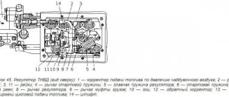
The high-pressure fuel pump (HPF, mod. CP3.3, Fig. 2) is designed to create a fuel reserve, maintain and regulate pressure in the fuel accumulator.
A fuel priming pump 2, driven by a shaft 9, and an electromagnetic pressure regulator 3 are attached to the fuel injection pump housing.
In the injection pump housing, three plungers 5 are located radially at an angle of 120° (Fig. 4), and a cam rotor 4 is installed on the drive shaft 3 (the cams are located at 120° intervals around the circumference of the rotor).
The injection pump drive shaft with a cam rotor has a gear drive from a gearbox, the input shaft of which, through the drive half-coupling, is in kinematic connection with the diesel crankshaft through distribution gears.
The fuel, which has passed through a coarse fuel filter with a moisture separator, is supplied under a pressure of 0.8...0.9 mPa by a fuel booster pump through a fine fuel filter to the inlet fitting of the injection pump.
Lubrication and cooling of fuel injection pump parts is carried out by diesel fuel entering the injection pump.
Under the influence of the created pumping pressure, the safety valve 2 allows fuel access through the supply channel 6 into the spaces above the plunger.
The advancing cam of the rotor moves the plunger upward, while the inlet of the inlet channel is closed and with further lifting of the plunger, the fuel is compressed in the space above the plunger.
When the increasing pressure reaches a level corresponding to that maintained in the high-pressure accumulator, the outlet valve 7 opens. The compressed fuel enters the high-pressure circuit.
The plunger delivers fuel until it reaches TDC (feed stroke).
Then the pressure drops and the outlet valve closes. The plunger begins to move downwards. For one revolution of the shaft, each (out of three) plunger makes one pumping stroke.
Since the fuel injection pump is designed for a large flow rate, at idle and at partial loads an excess of compressed fuel occurs, which is returned to the fuel tank through the pressure control valve 8 and the return line.
The pressure control valve sets the pressure in the high-pressure accumulator depending on the engine load, engine speed and thermal condition of the engine.
If the pressure in the accumulator is too high, the valve opens and some of the fuel from the accumulator
is discharged through the return line back to the fuel tank.
The pressure control valve is attached through a flange to the injection pump housing. The armature 10 presses the valve ball 9 to the seat under the action of the valve spring so as to separate the high and low pressure circuits.
The switched on electromagnet 11 moves the armature, applying additional force to press the ball against the seat.
The entire anchor is washed with fuel, which lubricates the rubbing surfaces and removes excess heat.
The high-pressure fuel accumulator (Rail) is a high-pressure fuel storage tank (Figure 5).
At the same time, the battery smoothes out pressure fluctuations that arise due to the pulsating fuel supply from the injection pump, as well as due to the operation of the injectors during injection due to the non-synchronism of the pressure pulses of the fuel doses coming from the injection pump and consumed through the injectors, as well as due to excess weight fuel located in the battery and playing the role of a damper for pulses of small doses of fuel entering and expended.
Battery 1 in general has the shape of a pipe, at the ends of which a fuel pressure sensor 7 and a pressure limiting valve 5 are installed.
Along the generatrix of the pipe perimeter there is a fitting for connecting high-pressure fuel lines 2; 3 and return drain fitting 4.
Fuel from the injection pump is directed through the high pressure line to the inlet fitting of the 3rd ramp
The fuel accumulator communicates with the injectors through high-pressure fuel lines connected to the accumulator outlet fittings.
The battery volume is constantly filled with fuel under pressure. The value of this pressure is maintained at a constant level and can be adjusted by valve 8 (Fig. 5) depending on the operating parameters of the diesel engine.
The pressure limiting valve maintains a certain amount of pressure in the accumulator, acting as a pressure reducing (safety) valve.
The valve body on the battery side has a channel locked by the valve core cone 6.
The spring presses the cone tightly against the valve seat at normal operating pressure so that the accumulator remains closed.
If the pressure in the accumulator exceeds the operating value, the cone moves away from the seat under the influence of pressure and the fuel under high pressure is discharged into the return line. As a result, the fuel pressure in the battery decreases.
The nozzle (Fig. 6) is designed to inject fuel into the diesel cylinder and provide the necessary fuel atomization. Diesel engines use CRIN2 type injectors manufactured (Germany).
The required timing of injection and the amount of fuel supply are provided by the action of the injector solenoid valve.
The moment of injection start in angle-time coordinates is set by the electronic control system of the diesel engine.
The electronic unit generates injector control signals based on “reading” the signals generated by the crankshaft speed sensors and the input shaft of the injection pump drive gearbox (sensors 1 and 2 in Fig. 2), installed in a coordinated relationship according to a certain scheme.
The operating principle of the nozzle is shown in Figure 7.
Fuel is supplied through the high-pressure line through the supply channel 4 to the injector nozzle 11, as well as through the fuel supply throttle opening 7 into the control valve chamber 8. Through the fuel outlet throttle opening, which can be opened by an electromagnetic valve, the chamber is connected to the return drain line 1.
When the throttle hole 6 is closed, the hydraulic force acting from above on the control valve piston exceeds the force of fuel pressure from below on the nozzle needle cone.
As a result, the needle is pressed against the nozzle seat and tightly closes the nozzle holes. As a result, fuel does not enter the combustion chamber.
When the solenoid valve 3 is activated, the armature of the electromagnet moves upward, opening the throttle hole 6.
Accordingly, both the pressure in the control valve chamber and the hydraulic force acting on the control valve piston are reduced.
Under the influence of fuel pressure on the cone, the nozzle needle moves away from the seat, so that the fuel enters the combustion chamber of the cylinder through the nozzle holes.
Control supply is an additional amount of fuel intended to lift the needle, which, after use, is diverted into the fuel return line.
In addition to the control supply, there are fuel leaks through the nozzle needle and the control valve piston guide. All this fuel is diverted into the return line, to which all other components of the injection system are connected, and returned to the fuel tank
The amount of injected fuel is proportional to the activation time of the solenoid valve and the pressure in the rail, and does not depend on either the engine speed or the operating mode of the fuel injection pump (time-controlled injection).
When the solenoid valve is de-energized, the armature is pressed down by the force of the valve closing spring and valve ball 5 closes the throttle hole.
After closing the fuel outlet throttle hole, the pressure in the control valve chamber again reaches the same value as in the battery.
This increased pressure forces the control valve piston down along with the spray needle. When the needle fits tightly to the nozzle seat and closes its holes, injection stops.
The fuel coarse filter is used to pre-clean fuel from mechanical impurities and water.
Due to the fact that the engine fuel injection pump is not equipped with a manual fuel priming pump, which is necessary to fill the fuel system with fuel without air, the filter design must contain a manual fuel priming pump.
In Fig. Figure 8 shows a fuel coarse filter with a manual fuel priming pump “PreLine 270”.
The sludge is drained from the filter through tap 5, located in the lower part of the moisture separator 4.
When operating a diesel engine at ambient temperatures below -25°C, the filter housing must be equipped with a fuel supply heater 3. The heater supply voltage is 24 V, power is 350 W.
Connection: plus and ground. The heater operates autonomously and turns on and off automatically at temperatures below +5°C.
The fine fuel filter is used for final fuel purification. The fine filter is non-separable. The fuel, passing through the curtains of the paper filter element, is cleaned of mechanical impurities.
The diesel air supply system (Fig. 9) consists of an air filter, a turbocharger, a charge air cooler, pipes, pipelines and mounting clamps.
A dry type air filter with replaceable paper filter elements is used to clean the air entering the cylinders.
The air filter (Fig. 10) consists of a housing 5, two filter elements 6 and 7, a cover 4 and rubber gaskets to ensure tightness.
A small (internal) filter element ensures air purification in the event of mechanical destruction of the outer filter element.
Attention! The suction of untreated air into the engine cylinders, which occurs due to depressurization of the intake tract, leads to a sharp decrease in engine service life.
To make it easier to monitor air filter clogging, a sensor is installed between the filter and the turbocharger, and a warning light is installed on the instrument panel.
As the filter becomes clogged, the vacuum in the inlet pipeline increases and when the value reaches 6.5 kPa, the alarm is activated, and the “Air filter clogged” warning lamp lights up on the instrument panel.
When the lamp lights up, the filter element should be cleaned or replaced.
The turbocharger (Fig. 11) consists of a centrifugal single-stage compressor and a radial centripetal turbine.
Boost control occurs by bypassing part of the exhaust gases past the turbine wheel when the boost pressure exceeds a certain value.
A bypass valve is built into the turbine housing of the variable turbocharger. The bypass valve lever is connected by an adjustable rod to an actuator connected by an air duct to the outlet pipe of the compressor housing.
Changing the thrust length of the turbocharger actuator during operation is not allowed.
Disassembly and repair of the turbocharger during operation are not allowed and must be carried out in a specialized repair shop.
8.12. Elements that are replaced on a car during its maintenance
8.12.1. Car GAZ-3309
When servicing the vehicle, the following elements must be replaced:
1. Non-separable fine fuel filter.
Filter designation: FT020–1117010.
Maintenance of the fine fuel filter consists of periodically draining the sediment.
To drain the sediment, you need to unscrew the filter plug and drain the sediment until clean fuel appears, then tighten the plug.
To remove air you need to:
- unscrew plug 3 (Fig. 8.9) on the fuel pump body and unscrew fitting 1 on the fine fuel filter by 1–2 turns;
- bleed the system using booster pump 2, when fuel appears, first tighten fitting 1, then plug 3.
Rice. 8.9. Removing air from the fuel supply system:
1 - fitting; 2 — booster pump; 3 - plug
2. Air filter element.
Element designation - 4301–1109013–10, 4301.1109013–20, GB-502 or EF-43K.
3. Non-separable oil filter.
Filter designation: FM009–1012005 or M5101.
When installing the filter on the housing, the rubber sealing gasket must be lubricated with engine oil and screw the filter onto the housing.
After the gasket touches the housing, tighten the filter another ¾ turn. Install the filter only by hand.
Instead of the FM009-1012005 or M5101 filter, it is allowed to install replacement filters X149 (France) and L37198 Italy) with the main dimensions:
- in diameter - 92–96 mm;
- height - 140–153 mm;
- on mounting thread ¾ -16UNF.
4. Filter element ShNKF 453473 for the power steering system reservoir.
When installing a non-separable tank YaMZ.993.003 for the power steering system, the tank is replaced as an assembly.
5. Fuel pre-filter.
The filter designation is PRELINE 270. Maintenance of the fuel pre-cleaning filter consists of periodically draining the sludge of water and particles from the reservoir.
To drain the sludge, you need to unscrew the drain plug and drain the sludge until clean fuel appears, then tighten the plug.
If dirty, replace the PRELINE 270 replacement filter element with a new one.
Spare parts for Trucks GAZ-3309
The Gorky Automobile Plant began producing the GAZ-3309 car in 1994. It consists of a diesel engine model GAZ-5441: four-stroke, 4-cylinder, air-cooled and turbocharged. GAZ-3309 is widely used for transporting industrial and agricultural goods on all types of roads. GAZ-3309 is a two-axle truck with rear axle drive, having modifications of a cargo platform with a tarpaulin with a carrying capacity of up to 4.5 tons and a cargo platform without a tarpaulin up to 4.35 tons. The trucks were equipped with both 4-cylinder engines and 6-cylinder engines with 150 hp.
GAZ-4301 has a single-disc closed dry friction clutch, a five-speed manual gearbox; rear suspension on longitudinal springs and hydraulic shock absorbers. Brake system GAZ-4301: working - dual-circuit, with hydraulic drive; parking – mechanically driven rear wheel brakes. The truck has a heated metal double cab with seat belt attachment points, as well as a mechanical power take-off and a hydraulic pump.
Gross weight, kg: 7400 Weight of transported cargo, kg: 3250 Weight of curb vehicle, kg: 3250 Engine power at crank speed 2200 min, kW (hp): 89 (116) Gas consumption at speed, l/100 km at 60 km/h: 29.6 Engine displacement, l: 4.15 Maximum speed, km/h: 80 Load capacity, kg: 3250
On the website you can buy GAZ-3309 spare parts in the GAZ-3309 spare parts catalog. Our specialists will advise you and help you choose the necessary GAZ-3309 spare parts for your car. By purchasing spare parts from Dynamics 76, you are guaranteed to purchase high-quality spare parts for the GAZ-3309.