Scheme of URAL 4320 engine electrical equipment, gear shifting and braking system
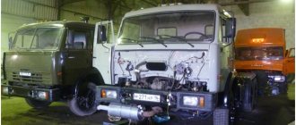
The layout of the Ural 4320 truck with high driving performance and increased cross-country ability makes this vehicle extremely versatile.
Ural 4320 is used both in geological exploration and by enterprises with difficult operating conditions for equipment, as well as the armed forces of the Russian Federation. Thanks to the well-thought-out layout of the URAL 4320 and the arrangement of various components and assemblies, it has established itself as a reliable vehicle in operation and practical in maintenance.
The successful combination of the URAL 4320 layout of the main components and assemblies in combination with a reliable and practical engine allows the URAL 4320 to be used both for transporting people and for delivering goods.
The universal design of the URAL 4320 chassis also allows it to be used as a tractor, dump truck or a platform for installing various equipment and special equipment based on the URAL 4320 design.
Historical reference
Pre-war period
From archival documents it follows that a group of engineers appointed by the Soviet leadership considered it expedient to use the BMW R-71 product as the basis for the future motorcycle..
German BMW R-71 model 1940
For reference: The group studied all commercially produced motorcycles available in those years. And based on a number of characteristics, she determined the most promising configuration, which was exactly what the BMW brand corresponded to. However, according to Soviet engineers, some of the components and assemblies, as well as the central wiring, needed modification to suit domestic operating conditions.
The project was approved by the Soviet leadership and already in 1940 pre-production samples were ready for testing, which had:
- The wiring diagram of the Ural motorcycle was based on a single-wire version (the metal frame acted as a “minus”), while BMW used a two-wire one;
- 6V voltage was chosen (in the post-war years, 12-volt equipment was considered promising);
- For stable operation on a lean fuel mixture, a manual ignition timing regulator was installed;
- To improve motorcycle performance in off-road conditions:
- a double-disc clutch was installed (the BMW R-71 was equipped with a single-disc clutch);
- In the gearbox, the final drive ratios have been increased.
The main feature of the first heavy domestic motorcycle was its simplicity:
- you could fix any breakdown along the way with your own hands;
- adjust the electrical system (the electrical wiring of the Ural motorcycle allowed this);
- clean and adjust the power system;
For reference: In pre-war times, more than 7,000 motorcycles entered service. Their production was carried out by the Moscow Motorcycle Plant (MMZ), the Gorky Motorcycle Plant (GMZ), the Leningrad and Kiev Motorcycle Plants (KMZ).
War time
With the outbreak of war, motorcycle production was urgently evacuated to Sverdlovsk and quickly launched at the Irbit motorcycle plant. The donor of the new production was all the equipment removed from the Moscow Motorcycle Plant. And the finished products went straight from the assembly line (pictured below) to the customer.
Directly from the factory, the militia went to the front on M-72 Ural motorcycles
Engine diagram URAL 4320
Diagram of the Ural-4320 engine with YaMZ four-stroke diesel engine with and without turbocharging with a power of up to 312 hp. With. environmental class from Euro-4. Below are diagrams of the Ural 4320 engine with a detailed description of the power supply system, engine electrical equipment and lubrication system.
Engine diagram URAL 4320
Ural 4320 vehicles are equipped with various diesel engine options with power up to 300 hp.
URAL 4320 engine diagram
Depending on the configuration, URAL 4320 is supplied in the following modifications:
- YaM3-236NE2 - six-cylinder engine with a power of 230 hp. and a working volume of 11.15 liters, developing torque of 882 Nm;
- YAM3-236BE - six-cylinder engine with a power of 250 hp. and working volume – 11.15 l, maximum torque – 1078 Nm;
- YaM3-238 - eight-cylinder engine 240 hp. and working volume – 14.86 liters, maximum torque – 882 Nm;
As you can see in the diagram of the URAL 4320 engine, the YaMZ power unit is installed on four load-bearing supports: one front, one rear, as well as two middle ones - left and right.
URAL 4320 engine diagram - engine mechanism
The URAL 4320 crank mechanism is designed to convert the reciprocating motion of the pistons into rotational motion, and vice versa. A detailed diagram of the URAL 4320 crank mechanism with a full description of the device and engine parts is presented below.
engine diagram URAL 4320 - Crank mechanism
The gas distribution mechanism URAL 4320 provides the intake and exhaust of inert substances in the YaMZ-236 / YaMZ-238 engine system. The timing diagram of the URAL 4320 can have either a fixed valve timing or one that can be adjusted depending on the crankshaft speed.
URAL 4320 engine diagram - timing belt
These units are liquid cooled. The power supply system in the URAL 4320 diagram is a mechanical in-line injection pump.
Scheme URAL 4320 - injection pump
The installation diagram for the drive units and power take-off modes in the URAL 4320 diagram is single-stage, attached to the gearbox housing on the right side and is intended to drive auxiliary units.
Diagram of the engine drive of the URAL 4320 units
The URAL 4320 lubrication scheme is designed in such a way as to clean, lubricate and cool the engine as efficiently as possible.
Lubrication diagram for the URAL 4320 engine
The lubrication system also serves to supply purified and cooled oil to the rubbing parts of the YaMZ-236 and YaMZ-238 engines to reduce the negative effects of friction, wear of engine components and parts, as well as optimal heat removal and removal of combustion products, slags and soot.
Cooling diagram URAL 4320
The URAL 4320 engine air supply circuit consists of an air filter, low pressure pipelines, connecting hoses and fastening parts.
Scheme URAL 4320 - cooling scheme
The URAL 4320 lubrication system operates on the principle of supplying oil to friction surfaces under pressure, as well as by splashing, in a self-lubricating manner.
Diagram URAL 4320 - lubrication diagram
The URAL 4320 lubrication system diagram includes a YaMZ-236/YaMZ-238 engine sump, an oil intake that provides primary oil purification and supply to the pump, a full-flow filter and a centrifugal oil purification filter, a radiator, a filler pipe, an oil level indicator, a breather, and a control -measuring instruments, lines and pipelines.
Diagram of the URAL 4320 lubrication system
The oil in the system is indicated on the general URAL 4320 lubrication diagram and is supplied under pressure to the rubbing parts, in particular to the main and connecting rod bearings of the crankshaft, as well as the camshaft bearings of the URAL 4320 engine.
Lubrication diagram URAL 4320
Thanks to the well-proven lubrication scheme of the URAL 4320, the rocker arm bushings, the main engine components, the fan drive fluid coupling, and the high-pressure fuel pump have a long service life.
Engine Modifications
| Model | Purpose, consumer | checkpoint | Main design differences | Clutch |
| YaMZ-236NE2-12 | Bus LiAZ-5256 - for spare parts | YaMZ-236L1 | YaMZ-236NE2-1 (base) V-shaped injection pump (12×13), design features see YaMZ-236NE-6 | YaMZ-182 |
| YaMZ-236NE2-16 | Bus "Neman-5201" - for spare parts | YaMZ-236L1 | YaMZ-236NE2-12 (base) T-shaped front support, compressor and generator drive, generator 6582.3701-03, EFU | YaMZ-182 |
| YaMZ-236NE2-24 | Cars, chassis “Ural-4320-40, -4320-41, -43203-41, -43206-41”, “Ural-4320-1912”, “Ural-5557-40, -5557-1112, -55571-40” ", truck tractor "Ural-44202-41", rotation buses "Ural-3255-41, -325512-41, -32552-41, -32552-47" and their modifications | YaMZ-236U2 (end splines) | YaMZ-236NE2-3 (base) | YaMZ-182 |
| YaMZ-236NE2-3 | Cars “Ural-43206-41”, “Ural-4320-40”, “Ural-5557-40”, “Ural-44202-41” - for spare parts | YaMZ-236U3 | YaMZ-236NE2-1 (base) Upper location of the TKR, exhaust gas supply system to the TKR, intake manifolds, oil crankcase with the deep part forward, extended oil level indicator, generator 1322.3771, k.v. pulley. 3-channel, V-shaped injection pump, connecting pipe for intake manifolds. Without inlet pipe, connecting pipe, fan casing. | YaMZ-182 |
| YaMZ-236NE2-31 | Buses LAZ-52523, -4207, -5207 - for spare parts | |||
| YaMZ-236NE2-36 | Cars MAZ-533602, MAZ-533702, -543202, -543302, -555102, -555402 and their modifications - for spare parts | |||
| YaMZ-236NE2-37 | Buses “Neman-5201, -52012” (Republican Unitary Enterprise “Experimental Plant “Neman”, Lida) | |||
| YaMZ-236NE2-6 | Buses LAZ-52523, -4207, -5207 - for spare parts | YaMZ-236L1 | YaMZ-236NE2-1 (base) V-shaped injection pump, cylinder block, intake manifolds, high and low pressure fuel pipes, h.v. pulley. 3-way with groove, TKR shifted towards the fan, gas exhaust system, bus oil sump, oil level indicator, compressor and generator drive Without fan impeller, fan casing, fan clutch, connecting pipe of the ONV, generator, but with its parts fastenings, EFU. | YaMZ-182 |
| YaMZ-236NE2-8 | Bus "Volzhanin-5270" - for spare parts | YaMZ-236L1 | YaMZ-236NE2-1 (base) Tractor type front support with clamp, k.v. pulley. with groove, bus oil sump, oil level indicator, compressor and generator drive Without fan impeller, fan casing, fan clutch, connecting pipe NVG, generator, but with fastening parts and drive belts | YaMZ-182 |
Direct supply of original: YaMZ engines, diesel generators, drives, gearboxes, PTO, spare parts in a full range.
Brake system URAL 4320 diagram
The diagram of the URAL 4320 brake system is presented in the form of a full-color schematic plan. The URAL 4320 brake system is designed to change the speed of movement or completely stop the URAL 4320, regardless of the speed, direction of movement and load-bearing load.
Brake system URAL 4320 diagram
The URAL-4320 brake system diagram is a combination of three brake systems - service, parking and auxiliary.
Scheme URAL 4320 brake system
The URAL 4320 is equipped with a pressure control system and brake condition monitoring system. The atmospheric cylinders contain sensors for signaling the minimum air pressure in the URAL 4329 brake circuit.
Scheme of the brake system URAL 4320
In the diagram of the URAL 4320 brake system, the brake drive is mixed (pneumohydraulic), dual-circuit, with separate braking of the wheels of the front and two rear axles. The control is carried out by a pedal in the driver's cabin, connected by levers and rods to a two-section brake valve.
Scheme URAL 4320-brake system diagram
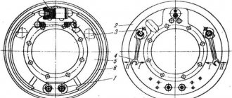
Diagram of the URAL 4320 service brake system with drum type and internal pads with complete interchangeability for all wheels. Each brake mechanism has two hydraulic cylinders housed in one housing.
diagram URAL 4320 - diagram of the brake system, service and parking brake
Brake pads are installed on supporting axles. The working brake mechanism is adjusted as the linings wear out by reducing the gap between the lining and the drum using eccentrics.
Electrical diagram –
1. Front lamp.2. Side turn signal repeater.3. Low beam headlight.4, 61. Connecting panel.5. Horn relay.6. Torch candle EFU.7. High-pitched electrical signal.8. Fuse.9. Pre-heater electric motor. 10. Coolant temperature indicator sensor. 11. Low tone electrical signal.12. Spark plug for pre-heater.13. High voltage source.14. Preheater electric motor switch.15. Heater spark plug switch.16. Generator.17. Voltage regulator.18. Electromagnetic valve EFU.19. Condenser filter.20. Torch relay.21. Engine compartment lamp.22. Voltage regulator cut-out relay.23. Additional resistor with electrothermal relay.24. Signal switch.25. Emergency oil pressure drop sensor.26. Oil pressure sensor.27. Oil filter contamination sensor.28. Sensor for emergency coolant overheating.29. Pre-heater electromagnetic valve.30. Solenoid valve, fan clutch.31. Battery switch interlock relay.32. Fan clutch activation relay.33. Fuel heater, preheater.34. Pre-heater solenoid valve switch.35. Fuel heating switch.36. Fan clutch switch.37. Thermal relay.38. Starter.39. Lower fuse block.40. Upper fuse block.41. Cabin heater switch.42. Heater motor resistance.43. Cabin light switch.44. Spotlight switch.45. Switch for road train sign lights.46. Heater electric motor.47. Rear fog lamp switch.48. Rear fog lamp relay.49. Right indicator lamp block. Signal indicators: 50. turning on the EFU;51. Vehicle direction indicators;52. Trailer direction indicators;53. Inclusions HOME;54. Switching on KOM.55. Fuse 6A.56. Fuse 10A.57. Central headlight switch.58. EFU power button.59. Hazard warning light switch.60. Turn signal switch.62. Turn signal switch.63. Auxiliary brake relay.64. Auxiliary brake switch.65. Spotlight.66. Portable lamp socket.67. Starter blocking relay.68. Starter and instrument switch.69. The instrument backlight switch is rheostatic.70. Starter activation relay.71. Brake light switch.72. Thermobimetallic fuse.73. Minimum pressure sensor.74. Foot switch for headlights.75. Brake fault warning switch.76. Battery activation button.77. Windshield washer control button.78. Fuel level sensor.79. Wiper switch.80. Sound signaling device (buzzer).81. Parking brake warning light.82. Semi-trailer folding angle indicator.83. Parking brake warning switch.84. Emergency coolant temperature indicator.85. Brake fault indicator.86. Indicator for minimum air pressure in the pneumatic system.87. Oil filter clogging indicator.88. Left indicator lamp block.89. Parking brake relay.90. Fuel reserve indicator.91. Tire pressure gauge.92. Fuel level indicator.93. Current indicator.94. Headlight high beam indicator.95. Speedometer.96. Tachometer.97. Alarm for emergency drop in oil pressure.98. Oil pressure indicator.99. Coolant temperature gauge.100. Two-pointer pressure gauge.101. Indicator for turning on the cross-axle differential lock.102. Cabin light.103. External launch socket.104. Reversing light switch.105. Battery switch.106. Switching sensor KOM.107. Switch on sensor DOM.108. Road train sign lantern.109. Rechargeable batteries.110. Windshield washer motor.111. Windshield wiper motor.112. Rear fog lamp.113. Rear lamp.114. Body signal switch.115. Reversing light.116. License plate light.117. Trailer plug socket.118. Cross-axle differential lock activation sensor.119. Underbody light.
gc-ural.ru
Relay block
The main relays are mounted on the front panel under the hood of the Ural.
p, blockquote 19,0,0,0,0 —>
p, blockquote 20,0,0,0,0 —>
There may be: horn relay, fan relay, starter relay, turn switches, parking brake relay, etc.
p, blockquote 21,0,0,0,0 —> p, blockquote 22,0,0,0,1 —>
That's all. And if you want to help supplement the material, write in the comments.
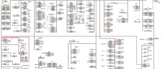
Electrical diagram of URAL 4320
The electrical circuit of the URAL 4320 is single-wire, where the negative potential of the voltage source of equipment and devices is connected to the ground of the vehicle. The negative terminal of the battery is connected to the ground of the URAL 4320 by a remote switch. Below is a high-resolution diagram of the electrical equipment of the URAL 4320.
Electrical diagram of URAL 4320
In the URAL 4320 electrical diagram, connections between wires and devices are made using plugs and connectors. For convenience, the colors of the wires in the URAL 4320 electrical diagram are presented in color.
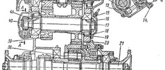
Transfer case URAL 4320 diagram
Transfer case URAL 4320 diagram. The transfer case (URAL 4320 diagram) is a mechanical, two-stage transmission, with an asymmetrical center differential, which is installed using four rubber shock absorbers on the URAL 4320 frame.
Transfer case URAL 4320 diagram
As you can see in the URAL 4329 transfer case diagram, the transfer case differential is of a planetary type with four satellites, 30 sun gears and 29 ring gears.
Scheme URAL 4320 - transfer case diagram
The moment from the sun gear is transmitted to the front axle drive shaft 35, and from the ring gear 29 to the rear axle drive shaft 21.
URAL-4320
If a box with a winch and an additional power take-off is installed on the URAL 4320 transfer case diagram, then when the bushing is turned on, the drive shaft gears are lubricated with high-pressure oil, which is supplied from the URAL 4320 transfer case housing using a plunger pump.
Wiring diagram URAL 4320
Electrical wiring diagram for URAL 4320 lighting, light and sound alarm systems. This diagram shows the wiring with electrical appliances, the central switch system for side lights, front and rear lights.
Wiring diagram URAL 4320
The URAL 4320 wiring diagram shows a list of the vehicle's electrical equipment according to the electrical diagram.
Scheme URAL 4320 - electrical diagram URAL 4320
| Item no. | Name | |
| 1 | Front marker lamp | PF133AB (PF130B or PF130AB-01) |
| 2 | Headlights | |
| 3 | Spotlight | 171.3711 |
| 4 | Connection panel | 17.3723 |
| 5 | Engine compartment lamp | PD308B |
| 6 | Lower fuse box | PR120 |
| 7 | Upper fuse box | PR120 |
| 8 | Portable lamp socket | PS400 |
| 9 | Cabin light | PK201-D |
| 10 | Central headlight switch | P 305 |
| 11 | Instrument lighting rheostat | VK416B-01 |
| 12 | Current indicator | AP171A |
| 13 | Illumination of control devices | — |
| 14 | Headlight high beam indicator | — |
| 15 | Cabin light switch | VK343.01.08 |
| 16 | Headlamp switch | VK343.02.06 |
| 17 | Rear fog light switch | |
| 18 | Starter and instrument switch | |
| 19 | Underbody lamp | FP103G |
| 20 | Reversing light | 2112.3711 |
| 21 | Reversing light switch | |
| 22 | Foot switch for headlights | P53 (P39) |
| 23 | Battery switch lockout relay | 901.3747 |
| 24 | Battery shutdown button | 11.3704 |
| 25 | Starter | 25.3708-01 |
| 26 | Battery switch | 11.3704-01 |
| 27 | battery | 6ST-190A or 6ST-190TR or 6ST-190TM |
| 28 | Back lamp | FP133AB |
| 29 | License plate light | FP134B |
| 30 | Rear fog lamp | 2412.3716 |
Steering diagram URAL 4320
Steering diagram for URAL 4320 with hydraulic booster. The steering consists of a steering column, a steering mechanism, a steering gear, and a hydraulic booster.
Steering diagram URAL 4320
As can be seen in the steering diagram, when the URAL 4320 steering wheel rotates, torque is transmitted to the distributor shaft. In this case, the shaft rotates relative to the screw at a small angle, simultaneously twisting the torsion bar.
Scheme URAL 4320 steering
Description of the book
Ural repair book
Operation of any Ural vehicle is impossible without knowledge of its structure, maintenance and repair features. It doesn’t matter who will carry out the necessary work - every driver is simply obliged to know the basic maintenance and troubleshooting procedures.
The Ural repair book contains all the necessary information that will help the owner understand the structure of the car, teach how to properly care for the car, timely maintenance and proper repairs.
The Ural repair manual is divided into chapters: Vehicle design (describes general information and vehicle specifications); Operating instructions (preparation for departure, recommendations for traffic safety); Malfunctions along the way (tips to help you in case of an unexpected breakdown on the road); Maintenance (detailed recommendations for all maintenance procedures); Repair instructions (engine, transmission, chassis, steering, brake system, and also includes assembly and disassembly work necessary during the repair process of the Ural); Electrical equipment (detailed manual for diagnosing and troubleshooting, the main units are described separately and detailed electrical diagrams of the Ural are given).
Any of the Ural repair procedures is given according to the principle from simple to complex: from the simplest maintenance operations, adjustments, replacement of parts, to global repairs with assembly and disassembly work.
All materials in the book are based on specific experience gained in the process of complete disassembly and assembly of the Ural by highly qualified auto mechanics.
Book “Ural-4320-10,4320-31. RE" is necessary so that diagnostics and repairs of the Ural can be done professionally and quickly even by the owner of the car who still has little practical experience.
You can download the Ural repair manual for free in pdf format . You just need to download it to your phone or tablet and you can use it in any situation on the road.
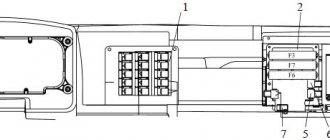
Fuse diagram URAL 4320
The URAL 4320 fuse circuit is designed to protect the vehicle's electrical circuit by opening the fuses and the current-carrying parts provided for this under the influence of a current exceeding a critical value.
Fuse diagram URAL 4320
1-relay for unloading terminal “15” (P2); 2-starter relay (P1); 3, 4, 6, 8, 9, 11 - fuse blocks; 5-relay for unloading terminal “15” (R3); 7-windshield wiper relay (R4); 10-rear fog lights relay; 12-diagnostic connector; 13-relay pneumatic brake signal switch (R12); 14-mirror heating relay (R11); 15-stop signal relay (R10); 16-horn relay (R9); 17-high beam relay (R8); 18-low beam relay (R7); 19-side light relay (R6); 20-relay additional rear fog lights (R5).
Fuse box
It is located in the instrument panel, behind the protective cover. On the cover of each block the current strength for which the fuses located under it is designed is indicated.
Scheme
Purpose
The remaining individual fuses are located under the hood (see diagram). For example, the heater power circuit is protected from short circuits by a 30 A bimetallic fuse 291.3722.
Description of modernized models
In later models, the fuse box itself is located in the same place, but made in a different form.
In some modernized Ural models, the fuse and relay box may be located in the panel on the right side, on the passenger side, behind a protective cover on which the current diagram will be printed.
Relay diagram URAL 4320
Fuse diagram URAL 4320
The upper fuse block protects: 1st insert - fog lamp circuit; 2nd insert - headlight lamp circuit: 3rd insert - circuit of portable and engine compartment lamps, power supply circuit for control lamp units; 4 - I - circuit of the cabin lamp, road train sign lights and brake light lamps; 5 - I - circuit of the electric motor of the heater and reversing light; 6 - I - power supply circuit for devices and buzzer.
The lower block protects the circuits: 1st insert - left side light; 2 - i - right side light and instrument lighting; 3 - i - low beam of the left headlight; 4 - i - low beam of the right headlight; 5 - i - high beam of the left headlight; 6 - i - high beam right headlight
Electrical equipment
The electrical equipment system is single-wire, the negative pole of power sources and consumers is connected to the vehicle ground. The negative terminal of the battery is connected to the vehicle ground using a remote switch. The sources of electricity are two batteries connected in series and a generator operating in conjunction with a voltage regulator. The connection of units and electrical equipment is carried out using wires with polyvinyl chloride insulation of various sections. The wires included in the bundles are made of a certain color to make them easier to find and easier to install. Single wires can be made in any color. The color of the wire can be indicated on the cuffs installed at both ends of the wire, the first letter of the color. The wires are connected to each other and connected to devices using plug connectors. The colors of the car's wires are included in Appendix 4. The car is equipped with a mechanically driven speedometer, electronic devices and systems: tachometer, generator with a rectifier unit, etc. To avoid damage to the flexible shaft of the GV300-05 speedometer, it is necessary to lay the flexible shaft in this way when installing and dismantling the instrument panel in such a way that the paint mark on the shaft shell is located outside the cabin directly behind the sealing sleeve of the flexible shaft through hole, while the flexible shaft must be routed without forming a loop behind the instrument panel. For reliable operation of these devices and systems, it is necessary to monitor the condition of the fuses installed in the blocks. Do not use non-standard fuses in the form of bent wire, bolts, washers, as in the event of a short circuit in the electrical circuit, this will lead to immediate failure of electronics-based products. A blown fuse should be replaced with another one of the same intended operating current. On truck tractors Ural 4420-10, Ural 4420-31 and Ural 44202-10, Ural 44202-31, a spotlight for illuminating the fifth wheel device is installed on the rear panel of the cab. On truck tractors Ural 44202-10, Ural 44202-31, a front spotlight is not installed. On vehicles Ural 43202-10, Ural 43202-31 and Ural 44202-30, Ural 44202-31, the lighting devices are installed in a non-sealed design; Cabin heater condenser, condenser filter 11.7904, heater motor condenser, tire pressure gauge with backlight are not installed.
Wiring diagram for the windshield washer control button: 1 - windshield washer motor; 2 — windshield washer control button; 3 - fuse
Rear fog lamp connection diagram: 1 - switch; 2 — rear fog lamp
Generator The waterproof alternating current generator (Fig. 86) is a 12-pole synchronous electric machine with a built-in rectifier unit VBG-7G or BPV7-100, with forced ventilation. The generator has the following terminals: “+” - for connection to batteries and load; two terminals “Ш” - for connection with the terminal “Ш” and “+” of the voltage regulator; pins “Ш” are made in the form of a two-pin plug block; “-” for connection to the voltage regulator housing; pin “~” - for connection to the tachometer.
| Technical characteristics at ambient temperature (15-35)°C | |
| Rated voltage, V | 28 |
| Rated current, A | 47 |
| Rated power, W | 1000 |
| Rotor speed at voltage 28 V, min-1: | |
| 1180 |
| 1900 |
| Maximum rotation speed, min-1 | 8000 |
| Excitation current, A | 1,5-1,7 |
Rice. 86. Car generator Ural 4320: 1 - fan; 2 - pulley; 3, 7 — ball bearings; 4 - rotor; 5 — brushes; 6 — brush holder cover; 8 — contact rings; 9 — rectifier block; 10 — cover from the side of the slip rings; 11 - stator; 12 - drive side cover
To avoid failure of the generating set, the following is not allowed:
- engine operation with the battery switch off;
- disconnecting the wires from the positive and negative terminals of the generator and disconnecting the plug connectors of the generator and the voltage regulator while the engine is running;
- checking the serviceability of the generator set by closing the jumper of the wires of the plug connectors “+” and “-” at the generator and voltage regulator;
- checking the serviceability of the generator using a test lamp or megohmmeter;
- turning on the battery with reverse polarity or connecting the positive terminal of the generator to the negative terminal of the battery;
- closing the voltage regulator terminals “+” and “Ш” to each other.
To ensure the generator operates properly, keep it clean. Check the operation of the generator using the current indicator. At average engine speed, the current indicator should show a charging current, the value of which decreases as the battery charge is restored. With a serviceable and fully charged battery, a serviceable generator and the correctly selected level of regulated voltage, the current indicator arrow should be at o. Clean the generator from dust by blowing it with compressed air. The generator should be repaired in a specialized workshop. To check the condition of the brush assembly, remove the brush holder. Check the ease of movement of the brushes in the brush holders. Replace brushes protruding from the brush holder channel by less than 5 mm. The force of pressing the brushes against the commutator when the spring is compressed to 17.5 mm should be 0.19-0.25 N (19-25 gf). If wear on the slip rings exceeds 0.5 mm in diameter, grind them. The minimum permissible ring groove diameter is 29.3 mm. The ball bearings are sealed and lubricated for their entire service life. If there is binding or excessive noise, replace the bearings. To check the serviceability of the generator on your car, you must have a DC voltmeter with an accuracy class of at least 1.5. A voltmeter is connected between the “+” and “-” terminals of the generator. The test is carried out with the batteries turned on at an average engine speed (about 2000 min-1). After running the engine for ten minutes, turn on the high beam headlights and record the voltmeter readings, which should be 26.6-29.2 V. Carry out a control check of the generator on a special stand that provides a smooth change in the rotation speed of the generator rotor up to 5000 min-1 and having measuring instruments with an accuracy class of at least 1.5. The circuit for checking the generator is shown in Fig. 87. If the generator is working properly, then its parameters must correspond to the technical specifications. A generator failure may occur due to a failure of the rectifier unit. Check the unit on a disassembled generator with the stator winding disconnected (Fig. 88). Check the rectifier unit from a battery connected to its terminals through a test lamp. When checking positive diodes, connect the battery wire to the positive bus of the rectifier unit, and connect the second wire alternately through the test lamp to the diode terminals. When checking negative diodes, connect the battery to the negative bus, and terminal 132
Rice. 87. Scheme for checking the electrical characteristics of the generator on the stand: 1 - generator; 2 - current indicator; 3 - voltmeter; 4 - load; 5 — rechargeable battery; 6 — additional resistance
Rice. 88. Scheme for checking the rectifier unit: a - checking positive diodes; b - checking negative diodes; I - diodes are turned on in a non-conducting direction; II - diodes are turned on in the conducting direction
Serviceable diodes of the rectifier unit conduct current in one direction and, therefore, the lamp lights up only when the diodes are turned on in the conducting direction. If the control lamp lights up or does not light up when it is turned on in both directions, then the unit diode is faulty. If a faulty diode is detected, replace the rectifier unit. Do not check the rectifier unit:
- from a voltage source of more than 24 V;
- from an AC source.
When installing the generator on the engine, keep in mind that the rear bolt securing the generator to the bracket is secured in a split support, and the leg of the front cover of the generator is attached without clearance. Therefore, when installing the generator, before tightening the generator mounting bolts, loosen the split mount pinch bolt, tighten the generator mounting bolts, and only then fully tighten the rear generator mount pinch bolt. Generator disassembly procedure:
- unscrew the two screws securing the brush holder and remove the brush holder;
- unscrew the coupling bolts and remove the cover from the side of the slip rings along with the stator;
- unscrew the nuts securing the phase leads from the rectifier block and separate the stator from the cover;
- Unscrew the pulley mounting nut and remove the pulley, fan, and support sleeve. Remove the cover from the shaft.
The generator is assembled in the reverse order. Voltage regulator A non-contact voltage regulator with three adjustment levels is used to maintain a constant voltage in the vehicle's electrical network. It is an electronic device based on semiconductor elements. Adjust the voltage using the switch located on the front cover of the regulator (Fig. 89). The position of the switch lever corresponds to the voltages: horizontal right (medium), horizontal left (maximum), vertical (minimum). Voltage level markings are located on the front cover of the regulator. The regulator is shipped from the factory with a medium setting level. If the ambient temperature is 0 °C or lower, move the switch lever to the “MAX” position to prevent undercharging of the batteries. At a temperature of 0 °C and above, move the lever to the “MIN” position to prevent the electrolyte from boiling away. If the batteries are undercharged or the electrolyte has boiled away, set the lever to the “SR” position. To avoid failure of the voltage regulator, do not short-circuit the “+” and “Ш” terminals to each other. Connect the wires according to the markings indicated on the generator and regulator.
Rice. 89. Voltage regulator for Ural 4320 cars: 1 - housing; 2 - switch; 3, 4, 5 — terminals
If you need to check the regulated voltage on your car:
- connect a voltmeter with an accuracy class of at least 0.5 with a scale of 0-30 V between the “+” terminal and the regulator body;
- start the car engine, set the crankshaft rotation speed to medium;
- turn on the high beam headlights as a load and record the adjustable voltage according to the voltmeter reading.
The voltage maintained by the regulator at 15-35 °C should be 26.5-27.9 V at the minimum level, 28.1-28.7 V at the average level, 28.7-30.1 V at the maximum setting level.
When checking on a bench (Fig. 90), the generator rotor speed at which the regulated voltage is checked should be 3500 min-1, and the load current should be 18 A. If the voltage is outside the technical specifications, replace the regulator.
Rice. 90. Connection diagram of the voltage regulator and generator when checking the regulated voltage on the stand: 1 - generator; 2 — ignition switch; 3 - voltage regulator; 4 - current indicator; 5 — rechargeable battery; 6 - voltmeter; 7 - load; 8 - ground switch
Rechargeable batteries Rechargeable batteries are designed to start the engine using a starter and work together with the generator at maximum loads. The vehicle is equipped with batteries filled with electrolyte. Upon special request, dry-charged batteries can be installed that are capable of retaining the charge initially given to them for one year from the date of manufacture. Basic data of rechargeable batteries: Rated voltage, V - 12 Capacity at 20-hour discharge mode and electrolyte temperature +25 °C, Ah - 190 Discharge current at 20-hour discharge mode, A - 9.5 Total volume of electrolyte in the battery , l - 12 Charge current, A - 19 Weight of battery with electrolyte, kg - 71 Fastening batteries Rechargeable batteries 1 (Fig. 91) are installed in container 10 on two side and middle supports. The batteries, after they are installed in the container, are secured with two upper clamps 13 and a front stop 4. The upper clamps 13 are fixed with front 9 and rear 12 wedge stops. The front wedge stops 9 are adjustable and secured to the cover b of the container with bolts 8. The rear stop 12 is welded in the upper rear part of the container 10. On the top panel of the container 10, guides 11 are welded for the correct installation of the clamp 13 relative to the stops 9 and 12. During maintenance of batteries on the car and removing batteries from the car:
- disconnect the batteries from the on-board power supply using the ground switch;
- remove the spring ring 14 of the lid locks 6 and open the locks;
- To carry out maintenance of batteries on a car, without removing the cover b from the car, lift it up and fold it onto bracket 3. Make sure that the cover b is securely fixed in a horizontal position.
To remove batteries from the car, remove cover 6 from the car by lifting it up and at the same time turning it relative to the brackets 2 on the bottom panel of container 10;
- If the batteries are equipped with protective terminal covers, remove them;
- Disconnect the wires to the starter and ground switch and the inter-battery jumper from the batteries. To service batteries on a vehicle, loosen the wires and jumpers to the batteries;
- remove the front stop 4 from the container 10 by lifting one end of the stop 4 until it comes out from behind the amplifier 5 of the container 10.
Rice. 91. Installation of batteries on Ural 4320 cars: 1 - battery; 2 - bracket; 3 — battery brackets; 4 — front stop; 5 — box body reinforcement; 6 — container lid; 7 — wing nut; 8 - bolt; 9, 12 — front and rear wedge stops; 10 - container; 11 — guides; 13 — upper clamp; 14 — lock ring
If the front stop 4 is clamped between the battery 1 and the amplifier 5, push the batteries into the container until it stops, then remove the stop 4. If the wires are not disconnected from the battery, lift the handles of the batteries 1 together with the wires and, holding them, remove the stop 4; remove the upper clamps 13 from the container 10. If the clamp 13 is clamped between the battery 1 and the rear wedge stop 12, use a screwdriver or a bit inserted into the hole at the end of the clamp to remove the clamp.
- To service the batteries on the car, slide the batteries one by one onto the hinged lid 6 of the container.
To remove batteries from the car, slide one battery onto bracket 3 and remove it from the car. Then slide the second battery onto the bracket and remove it. When sliding batteries 1 out of container 10 onto bracket 3 and removing them from the vehicle, take precautions to prevent an unsecured battery from falling. Install the batteries on the vehicle and secure them in the reverse order. Make sure that the upper clamps are installed in the guides I. Otherwise, the clamp 13 will not interact with the wedge stops 9 and 12 and the battery will not be secured, which may cause its destruction. Do not allow guides 11 to deform when installing and securing the battery. When installing and securing the battery, do not allow pinching and sharp bends of the wires to the starter and the ground switch, bending of the tips, as well as harmful contacts of the wires with the metal parts of the container. After installing the batteries on the car, adjust the position of the front wedge stops 9, to do this, loosen the tightening of the bolts 8 securing the stops 9 to the cover 6, move the stops 9 along the elongated holes of the cover 6 away from you until they stop and tighten the bolts 8. Adjust the position of the front wedge stops 9 on the closed cover 6 of container 10 after installing batteries 1 and upper clamps 13 into the container. Preparing dry-charged batteries for operation The procedure for preparing batteries to put them into working condition:
- remove the protective casing and cover, clean the batteries from dust and the terminal bolts from grease;
- Unscrew the plugs from the filler holes, remove the sealing gaskets and clean the ventilation holes in the plugs. For polyethylene plugs that have a protrusion, cut it off and clean the ventilation ducts;
- fill the electrolyte with the density indicated in table 5.
Table 5 Electrolyte density
| Climatic zones and regions. Average monthly air temperature in January, °C (GOST 16350-70) | Season | Electrolyte density, normalized to 25 °C, g/cm³ | |
| bay | fully charged battery | ||
| Cold with climatic districts; very cold, (minus 50 – minus 30) cold (minus 30 – minus 15) | Winter. Summer All year round | 1,28 1,24 1,26 | 1,30 1,26 1,28 |
| Moderate (minus 15 – minus Hot (minus 15 – plus 4) Warm, humid (0 – plus 4) | All year round | 1,24 1,22 1,20 | 1,26 1,24 1,22 |
| Note. The electrolyte density may deviate from the values given in the table by ± 0.01 g/cm³ | |||
Prepare the electrolyte by diluting battery sulfuric acid GOST 667-73 (but not technical) in distilled water GOST 6709-72. In this case, refer to Table 6.
Table 6 Preparation of 1 liter of electrolyte of the required density
| Electrolyte density, normalized to 25 °C, g/cm³ | Amount of water, l | Amount of acid with a density of 1.83 g/cm³ at a temperature of 25 °C | |
| l | kg | ||
| 1,20 1,22 1,24 1,26 1,28 1,40 | 0,859 0,839 0,819 0,800 0,781 0,650 | 0,200 0,221 0,242 0,263 0,285 0,423 | 0,360 0,404 0,444 0,484 0,523 0,776 |
When preparing the electrolyte, pour the acid into water, but not vice versa. The temperature of the electrolyte poured into batteries should be 15-30 °C. After soaking for 2 hours, bring the electrolyte level to 10-15 mm above the safety shield. The electrolyte temperature before turning on the battery for charging should not exceed 30 °C. Charge the battery with a current of 19 A until abundant gas evolution occurs in all batteries, and the voltage and density of the electrolyte remain constant for 2 hours. During the charging process, the temperature of the electrolyte should not exceed 45 ° C. When the electrolyte temperature reaches 45 °C, the charging current should be reduced by half and the charging time should be increased accordingly, or charging should be stopped while the electrolyte cools to a temperature of 30-35 °C. During the charging process, the electrolyte density increases and by the end of the charge reaches the value indicated in Table 5, taking into account the temperature correction according to Table 7. At the end of the charge, if the electrolyte density, measured taking into account the temperature correction (see Table 7), will differ from standards, adjust the electrolyte density by adding distilled water when the density is above normal, or by adding electrolyte with a density of 1.40 g/cm³ when the density is below normal. After adjustment (to mix the electrolyte), continue charging for 30 - 40 minutes. Table 7 Dependence of electrolyte density on temperature correction
| Electrolyte temperature, °C | Amendments to densimeter readings, g/cm³ |
| 46 - 60 45 - 31 30 - 20 19-5 plus 4 - minus 10 minus 11 - minus 25 minus 26 - minus 40 minus 41 - minus 55 | plus 0.02 plus 0.01 0.01 0.00 minus 0.02 minus 0.03 minus 0.04 minus 0.05 |
0.5 hours after the end of charging, set the electrolyte level to 10 - 15 mm above the safety shield, screw in the plugs, thoroughly wipe the surface of the battery with a rag moistened with a 10% solution of ammonia or soda ash, then wipe with a rag moistened with water and wipe dry. Install the cover and protective cover. In special cases, if it is necessary to very quickly put dry-charged batteries into operation, it is allowed to install them on cars without checking the density of the electrolyte after 20 minutes of impregnation, provided that the shelf life of the batteries does not exceed one year and the bringing into working condition is carried out at the temperature of the batteries and the electrolyte being poured not lower than plus 15 °C. If it is necessary to urgently commission dry-charged batteries stored at subzero temperatures down to minus 30 °C, fill in electrolyte with a density of (1.26-1.28) g/cm³ at a temperature of (38-42) °C. In this case, prepare the electrolyte in two stages according to the table. 8. Install the batteries filled with electrolyte into the car after one hour of exposure. Table 8 Electrolyte preparation
| Stage | Density of the resulting electrolyte, g/cm³ | The amount of added sulfuric acid with a density of 1.83 g/cm³ |
| Preliminary dilution is made in advance, taking into account the time required for the electrolyte to cool to 15 ° C, and is stored in a heated room | 1.20 - 1.21 at 15 °C | 0.24 per liter of water |
| Final preparation is carried out immediately before pouring | 1.26 - 1.28 at 40 °C | 0.13 per liter of electrolyte obtained |
The electrolyte level should be 10-15 mm above the safety shield. As soon as possible, fully charge the battery and bring it to normal. Procedure for using batteries During operation, do not connect the battery terminals to each other for spark testing. Based on the density of the electrolyte, taking into account the temperature correction, determine the charge of the battery (Table 9). If a battery is discharged by more than 25% in winter and more than 50% in summer, remove it from service and charge it. Table 9 Determination of acceptable battery discharge
| Climatic zones and regions. Average monthly air temperature in January, °C | Seasons | Density of battery electrolyte, charged to 100%, g/cm³ | Permissible decrease in electrolyte density when discharging batteries | |
| Cold, climatic. areas: very cold, minus 50 – minus 30 cold, minus 30 – minus 15 Moderate: minus 15 – minus 8 Hot: minus 15 – plus 4 Warm, humid: 0 – 4 | All year round | 1,30 1,28 1,26 1,24 1,22 | by 50% in summer, g/cm³ | by 25% in winter, g/cm³ |
| 1,22 1,20 1,18 1,16 1,14 | 1,26 1,24 1,22 1,20 1,18 | |||
In winter, add water immediately before starting the engine. If the electrolyte level drops or splashes out, top it up. In this case, the density of the electrolyte being added must correspond to its density in the battery. If electrolyte gets on the surface of the battery, remove it with a clean rag soaked in a 10% solution of ammonia or soda ash. Then wipe the surface with a cloth soaked in water and wipe dry. Store batteries in a dry charged state at room temperatures from minus 40 to plus 60 °C. The plugs with sealing disks must be tightly screwed into the batteries, the bolts and nuts to the terminals must be lubricated with a thin layer of lubricant. The main malfunctions of rechargeable batteries and methods for eliminating them are given in the section “Possible malfunctions and methods for eliminating them.” Lighting and signaling system Lighting and signaling devices include two headlights, front and rear lights, a license plate light, a spotlight, a reversing light, a cabin lamp, an engine compartment lamp and instrument lighting lamps, warning lamps located on the instrument panel. The front lights serve as side marker lights and front turn indicators, the rear lights serve as side marker lights, rear turn indicators and a STOP signal. The headlights are turned on by the central light switch 18 (see Fig. 15) in position I, the high or low beam is turned on by the foot switch. In positions I and II of the central switch, the side lights and instrument lighting lamps are turned on. The spotlight is turned on by a separate switch only in position I of the central light switch. When installing the body light, connect it to the underbody light circuit. Sound signaling is carried out by high and low tone electrical signals. The signals are activated by a switch installed in the pneumatic valve. Air enters the valve from the pneumatic system through the air bleed valve. Turning and braking alarm. The turn indicators are activated by a switch mounted on the steering column. When you turn the switch knob clockwise, the right turn signal lamps turn on: in the front light, in the side repeater and in the rear light. Turning the knob counterclockwise turns on the left turn signal lights. The switch returns to its original position automatically. A transistor relay interrupter provides intermittent light signaling. If the lamp in the headlights is faulty, the turn signal indicator lamp on the instrument panel does not light up. When you press the brake pedal, the rear brake lights turn on. All turn indicators are turned on in flashing mode (the vehicle is in emergency condition) using a special switch, and the warning light in the handle lights up. The remaining sound and light alarms are activated by the corresponding sensors or switches. Headlights. The direction of the headlights is adjusted by two screws located under the headlight rim. Screw 10 (Fig. 92) is designed to regulate the direction of light in the vertical plane (up and down), and screw 9 in the horizontal plane (right and left).
Rice. 92. Headlight 401.3711 (FP22VV1): 1 - outer rim; 2 - gasket; 3 - lamp; 4 — optical element; 5 — headlight housing; 6 — block; 7 - casing; 8 — casing holder; 9, 10 — adjusting screws
To adjust, place the car without a load on a flat horizontal platform in front of a vertical screen at a distance of (7.5 ± 0.3) m to the headlight lenses and, having removed the rims of both headlights, turn on the lights. The light beam of headlights 401.3711 and FG122VV1 with the “European” light distribution system is adjusted in low beam mode and should give a light zone in the lower part and a dark zone in the upper part on the control screen (Fig. 93). The dividing line of the light and dark zones should be horizontal and coincide with the line DD on the left side of the screen, from the inflection point P directed upward at an angle of 15° to the horizontal on the right side of the screen. Permissible maximum deviations in the horizontal and vertical planes of the inflection points from the intersection points of the left and right vertical lines with the DD line (± 35) mm. After completing the adjustment, put on the headbands and secure them, making sure that the light spot does not move. Replace headlight bulbs with darkened bulbs before they burn out. When replacing a burnt-out lamp, restore the seal of the optical element. The lamps used on the car and their characteristics are given in Appendix 7.
Rice. 93. Screen markings for headlight adjustment 401.3711 (FG122VV1): I - headlight center lines; II - site level; h - 230 mm (for cars Ural 4320-10, Ural 4320-31); h - 190 mm (for cars Ural 43202-10, Ural 43202-31)
The vehicle is equipped with a rear fog light, which is designed to indicate the vehicle in poor visibility conditions.
Attention! It is prohibited to drive a vehicle with the rear fog light on in normal visibility conditions. Fuses The heater power supply circuit is protected from short circuits by a bimetallic fuse. 291.3722 for 30 A. The upper fuse block (Fig. 94) protects: 1st insert - fog light circuit; 2nd insert - spotlight circuit; 3rd insert - circuit of portable and engine compartment lamps, power circuit of control lamp units; 4th - circuit of the cabin lamp, road train sign lights and brake light lamps; 5th - circuit of the electric motor of the heater and reversing light; 6th - power supply circuit for devices and buzzer. The lower block protects the circuits: 1st insert - left side light; 2nd - right side light and instrument lighting; 3rd - low beam of the left headlight; 4th - low beam of the right headlight; 5th - high beam of the left headlight; 6th - high beam right headlight
Rice. 94. Electrical diagram of the fuse box: 1-6 insert