Hydromechanical gearbox ⭐ consists of:
- torque converter;
- manual transmission.
In passenger cars, hydromechanical gearboxes with planetary mechanical gearboxes are most widespread. Their advantages:
- compact design;
- less metal consumption and noise;
- longer service life.
Disadvantages include:
- complexity;
- high price;
- reduced efficiency.
Gear shifting in these boxes is carried out using friction clutches and band brake mechanisms. At the same time, when one gear is engaged, some of the friction clutches and band brake mechanisms slip, which also reduces their efficiency.
The role of automatic transmission with hydromechanical control
To instantly start after pressing the gas pedal, and to protect the engine from overload, a transmission is installed in the car. It is also capable of changing torque, accelerating or decelerating the car. This transmission unit is called a gearbox - gearbox.
According to the type of gear shift, manual and automatic transmissions are distinguished:
Hydromechanical control facilitates and simplifies the driver’s work, removing some of the “responsibilities”. The smoothness and quietness of the automatic transmission increases driving comfort when starting and accelerating. The GMP also protects the engine and gearbox from dynamic loads that the driver can create by constantly “squeezing” the gas.
Main elements of a hydromechanical gearbox:
Read 5 Decent Automatic Motorcycles
Torque converter functions
A hydromechanical gearbox operates due to the movement of fluid pumped by an oil pump. The main “consumer” of oil is the torque converter (GDT). The gas turbine engine converts and transmits torque from the crankshaft to the transmission through fluid action.
Structurally, a gas turbine engine is a set of bladed wheels “locked” in a sealed donut-shaped chamber:
The hydromechanical transmission begins to work when the engine starts: the oil pump and pump wheel turn on. Liquid gets onto the wheel blades and spins around the axis of the gas turbine engine. Under the influence of centrifugal force, the oil is thrown onto the turbine blades, passes through the reactor and returns to the pump wheel. Under the pressure of the flow, the turbine blades begin to rotate, transmitting torque along the shaft to the gearbox.
The higher the engine speed, the faster the turbine wheels rotate, and the torque decreases. Without the reactor, the donut would only operate in fluid coupling mode, transmitting rotation without transformation. At the moment when the speeds of the pump and turbine are equalized, the reactor begins to rotate freely, increasing the pressure of the liquid falling on the pump blades.
Most of the engine energy is spent moving and heating the oil in the gas turbine engine. As a result, overall efficiency decreases and fuel consumption increases. To eliminate this drawback, a locking clutch with a friction lining is installed in the donut. When the clutch is engaged, the engine and transmission are firmly coupled, and torque is transmitted without loss.
The torque converter gear ratio reaches a maximum of 2.5 - 3, which is not enough for stable engine operation in different vehicle driving modes. It is not possible to engage reverse gear, since the wheels of the gas turbine engine only rotate in one direction. To compensate for these shortcomings, the hydromechanical gearbox is equipped with an additional unit.
Shifting the automatic transmission gear selector on the go
Hydrodynamic transmission
Fluid dynamic transmissions use dynamic pumps and turbines to transmit power. The working fluid in hydraulic transmissions is supplied from a dynamic pump to the turbine. Most often, a hydrodynamic transmission uses bladed pump and turbine wheels located directly opposite each other, so that the fluid flows from the pump wheel directly to the turbine wheel, bypassing the pipelines. Such devices that combine a pump and turbine wheel are called fluid couplings and torque converters, which, despite some similar elements in the design, have a number of differences.
Fluid coupling
A hydrodynamic transmission consisting of a pump and turbine wheel installed in a common crankcase is called a fluid coupling . The moment on the output shaft of the hydraulic coupling is equal to the moment on the input shaft, that is, the fluid coupling does not allow changing the torque. In a hydraulic transmission, power can be transferred through a hydraulic coupling, which will ensure smooth operation, a smooth increase in torque, and a reduction in shock loads.
How does a planetary gearbox work?
Its operating algorithm is extremely simple. Gear shifting on a planetary hydromechanical transmission is carried out using friction clutches. Also, to smooth out impacts when downshifting, a special brake band is used. It is when the “brake” operates that the torque transmission force decreases. But at the same time, gear shifting is smoother than that of shaft analogues.
The planetary transmission is based on a hydraulic transformer. This element is located between the engine and gearbox. HDF consists of several components:
This element is popularly called a “donut” because of its characteristic shape.
When the engine is running, the pump impeller rotates along with the flywheel. The lubricant penetrates inside the pump and then, under the influence of centrifugal force, begins to rotate the turbine. Oil from the last element penetrates into the reactor, which performs the function of smoothing out shocks and shocks, and also transmits torque. Oil circulation is carried out in a closed circle. The car's power increases as the turbine wheel rotates. Maximum torque is transmitted when the machine moves from a standstill. In this case, the reactor is in a stationary state - it is held by a coupling. When the car picks up speed, the turbine and pump speeds increase. The coupling wedges and the reactor rotates at increasing speed. When the revolutions of the last element are maximum, the torque converter will enter the clutch operating state. This way it will rotate at the same speed as the flywheel.
Planetary mechanism
In most modern automatic transmissions, the torque converter operates in tandem with a planetary system. It is responsible for transmitting torque to friction clutches. In the simplest version, the force is directed to the central gear (sun gear). Two additional satellites (auxiliary gears) are in constant mesh with the central gear thanks to the teeth applied to these elements. The satellites are not fixed, but rotate freely around their axes. The gear mechanism is located inside the crown wheel, which, depending on the gear engaged, is fixed or begins to move. At the moment the ring gear is fixed, the driven shaft begins to move (force is transmitted to it). Otherwise, the satellites transmit torque to the ring gear, leaving the driven shaft stationary. To change gears, planetary automatic transmissions are equipped with friction clutches. Each of them looks like several disks, which are thin plates of smooth metal. Each plate is coated with a special friction compound that prevents wear. On some of them you can find slots. Gaskets are located between the couplings. They are pressed against each other using a hydraulic piston that operates by supplying working fluid. As the pressure in it increases, the clutches close tightly, becoming almost a single whole. After the fluid pressure in the hydraulic piston drops, the friction discs return to their place using a spring. The operation of friction clutches is closely related to the functioning of brake and planetary mechanisms. At these moments, commands from the gearbox control system and engine torque are transmitted. Without their participation, engine braking and towing launching are not possible. The mechanical unit operates smoothly and clearly.
planetary system
Important! In the neutral position, the clutches and brakes are turned off. When accelerating and changing gears, the clutches begin to operate, and the planetary systems rotate synchronously.
Fluid mechanics design
GMFs use simple step or planetary mechanisms with electronic control. The principle of operation of the hydromechanical gearbox in both versions is to change the rotation speed of the output shaft due to different gear ratios.
How does a shaft gearbox work?
The design of a shaft-type hydromechanical gearbox is similar to a manual gearbox. Torque conversion occurs in steps through the inclusion and disengagement of gears located on parallel shafts. The number and size of gear pairs correspond to a certain gear ratio.
The primary, input shaft receives torque from the torque converter. Through a pair of permanently meshed gears, power is transmitted to the output shaft and then to the wheels. To obtain direct transmission, an intermediate shaft is added to the design, and the primary and secondary shafts are placed on the same axis.
To expand the speed range, multi-shaft designs with 4 or more shafts are used. At the same time, the operation of the box becomes more complicated, its dimensions and weight increase. Similar GMPs are found on tractor-trailers.
Gear drives are controlled by friction multi-plate clutches. The clutch becomes a brake when connected to the GMT housing. To engage the locking, the oil pump supplies hydraulic pressure to the clutches. Thanks to the clutches, the speed switches smoothly, and the use of a hydraulic drive speeds up braking.
Shaft-type hydromechanical gearboxes do not cope well with the growing thrust from increasing vehicle load capacity and tightening requirements for fuel efficiency. An increase in parameters significantly increases the weight and dimensions of the structure. For these reasons, shaft gearboxes are replaced with planetary gears.
How does a planetary gearbox work?
Engineers prefer to install a planetary mechanism in a hydromechanical gearbox instead of a stepped design for the following reasons:
Automatic transmission reset, calibration and adaptation
A simple planetary gear consists of central gears: with internal teeth - the crown, with external teeth - the sun. Between them, satellite gears are rolled, the axes of which are fixed to the carrier frame. Depending on the design, the carrier is connected to the output shaft or ring gear.
The design of the planetary gearbox determines its operating principle. To change the torque of the torque converter, one of the elements of the planetary gear is rotated, and the other element is braked. The third element becomes the driven element, and its speed is determined by the number of teeth of all gears.
To achieve direct transmission, the carrier and sun gear are rigidly connected. The crown cannot rotate relative to the fixed system, so the mechanism rotates as a single unit. The gear ratio in this case is 1.
To obtain reverse gears, the central gears rotate in one direction. To do this, stop the satellites, blocking the carrier.
Brake bands or friction discs are used as planetary gearbox brakes. The locking elements operate automatically based on an electronic signal.
Electronically controlled automatic transmission
As an example of a modern automatic transmission with electronic control, consider the six-speed gearbox 09G from the Japanese concern AISIN.
The automatic transmission consists of a torque converter, a mechanical planetary gearbox with multi-disc clutches and multi-disc brakes, a hydraulic system, cooling and lubrication systems, and an electrical system.
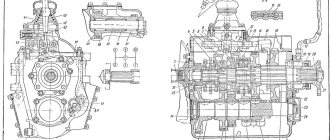
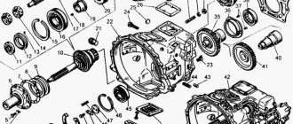
Rice. Section of the automatic six-speed gearbox 09G: K – multi-plate clutches; B – multi-disc brakes; S – sun gears; P – satellites; RT – carrier; F – overrunning clutch; 1 – turbine wheel shaft; 2 – driven gear of intermediate gear; 3 – liquid pump
The planetary series are combined according to a scheme developed by Lepelletier. The engine torque is supplied to a single planetary gear set. Next it goes to the Ravigneaux dual planetary gearset.
Rice. Lepelletier two-gear planetary system: a – conventional planetary gearbox; b – Raviño planetary gearbox; 1 – turbine wheel shaft; P1 – satellite ring gear H1; P2 – satellite of sun gear 2; P3 – satellite ring gear 1; S1 – sun gear 1; S2 - sun gear 2; S3 - sun gear 3; H1 – ring gear 1; H2 – ring gear 2
The single planetary gear set is controlled by multi-disc clutches K1 and K3 and multi-disc brake B1. The number of satellites in the planetary gears is selected depending on the transmitted torque.
The twin planetary gear set is controlled by a multi-disc clutch K2, a multi-disc brake B2 and an overrunning clutch F. The clutch control system includes dynamic pressure compensation devices that make the clutches operate independently of the rotation speed. Clutches K1, K2 and K3 serve to supply torque to the planetary gears, and with the help of brakes B1 and B2, as well as the overrunning clutch, the reactive torques are transmitted to the gearbox housing.
The pressure in the clutch and brake working cylinders is changed by control valves.
Overrunning clutch F is a mechanism that operates in parallel with the brake.
Types of fluid mechanics
For a long time, automatic transmissions were installed exclusively on middle-class and premium cars. Today, the unit has received widespread use and is becoming increasingly popular among car enthusiasts. Automatic transmissions can significantly increase comfort while driving, but it is worth considering that such units differ in types, each of which has its own advantages and disadvantages. Having understood the principle of operation of hydromechanical transmissions, it will be possible to decide which type of automatic transmission is suitable for a particular driver. It is worth mentioning the following types of hydromechanical gearboxes:
Robotic units and automatic transmissions are devices whose purpose is to simplify the driver’s interaction with the transmission.
Purpose of a combined transmission of a passenger car
The lifestyle of modern drivers is changing significantly and today more and more demands are placed on creating optimal comfortable conditions while driving. Standard car components are undergoing significant changes; among the most striking examples are the combination of mechanical and hydraulic gearboxes. If we talk about hydromechanical transmission and what it is, the first step is to understand what its purpose is. The main difference is the smooth change in rotational motion. Lighter control made it possible to abandon the use of a clutch, since the combined gearbox is responsible for all processes. With automatic transmission, we can talk about the following situations regarding driving a car:
- When changing gears, the transmission is disconnected from the power unit.
- If road conditions change, the amount of torque will also change.
Using an automatic transmission in a car allows you to get several undeniable advantages. In addition to the automation of gear shifting, it is also worth noting the increased performance characteristics of the power unit and gearbox and the improved cross-country ability of the vehicle in off-road conditions.
Automatic hydraulic box
Electronic part of hydromechanical automatic transmission
In a hydromechanical automatic transmission there is no clutch, so each gearbox stage is equipped with a switching element. The operation of the elements is controlled by an electronic computer unit connected to the engine control unit. During gear changes, the engine speed is automatically adjusted, which helps to achieve optimal performance of the unit.
The electronic control system of the hydromechanical transmission is divided into subsystems:
To automate control, in addition to the computer, the system includes electric valves, sensors, amplifiers, regulators, corrective elements, etc. Electrovalves - solenoids, are located in the valve body, and upon a signal from the ECU, they open the hydraulic plate channel for the passage of fluid to the clutches, torque converter and other components.
Depending on the position of the selector, the ECU operates according to a software algorithm stored in memory:
Which is better and more reliable, CVT or automatic?
“Smart” control conducts self-diagnosis to correct the operation of the GMF. For example, if the oil in the box is dirty, then the pressure in the system drops. To protect components, the ECU can block gear shifting, redistribute the load between electric valves, and prohibit the inclusion of the torque converter. The computer records malfunctions and failures in the box in the form of codes.
The computer can adapt, choosing the appropriate mode for the driving style, acceleration dynamics and braking style. Adaptation reduces gearbox wear by reducing the number of switchings. This increases driver comfort and traffic safety.
What is hydraulic transmission
A hydraulic transmission is a set of hydraulic devices that make it possible to connect a source of mechanical energy (engine) with the actuators of a machine (car wheels, machine spindle, etc.).
A hydraulic transmission is also called a hydraulic transmission. Typically, in a hydraulic transmission, energy is transferred through fluid from a pump to a hydraulic motor (turbine).
Depending on the type of pump and motor (turbine), a distinction is made between hydrostatic and hydrodynamic transmissions .
Prospects for using a hydromechanical gearbox
The hydromechanical gearbox is constantly being improved:
A hydromechanical gearbox with a planetary mechanism has great promise. The transmission is suitable for low-power and heavy-duty engines by adding new planetary gears and varying gear ratios. New technical solutions increase vehicle efficiency. Adding steps eliminates “dips” in gear shifting, achieving maximum smoothness.
Manufacturers produce HMFs of different sizes for engine power from 50 to 1500 kW. As the load capacity of special equipment increases, the efficiency and traction characteristics of the transmission increase.
The development of intelligent automated control and diagnostic systems is aimed at increasing vehicle efficiency and ensuring driver safety. The hydromechanical gearbox is adapted for automation, which opens up great opportunities for expanding the functionality of mechanisms and systems.
Source
Hydromechanical gearbox: operating principle and design
The classic design of a car implies the presence of two required blocks:
This description is suitable for a manual transmission that has been familiar to motorists for many decades. But over time, as technology developed, other variations of the gearbox unit began to appear, providing the person behind the wheel with greater comfort of movement.
Transmission is one of the basic components of a car. Thanks to it, torque is transmitted from the car engine to the wheels. In the automotive industry, for many years the manual transmission reigned supreme, incorporating the blocks described above in its design. The driver had to perform three sequential operations:
But the situation has changed, engineers have created a gearbox without a clutch pedal. In this case, the process of driving a car is greatly simplified for a person: the ECU makes the transition to the desired gear itself. Control is carried out by the gearbox selector, brake and gas pedals.
When moving away, the driver depresses the brake, moves the selector to position D (Drive), releases the brake, and starts driving. The automatic transmission shifts to 1st gear, 2nd and beyond, depending on the speed of the car, the position of the gas pedal, engine speed and other factors, which are monitored by a variety of sensors.
This process is ensured by the use of several technologies, the hydromechanical gearbox among which is the most famous, “tested” in production and reliable. In it, changing gears on clutches is carried out by circulating transmission oil under pressure through the box.
A modern hydromechanical transmission is a complex device consisting of the following main components:
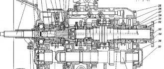
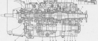
The latter is not a typo; the automatic transmission is really based on “mechanics”, structurally supplemented by automatic switching units with a torque converter - hence the name of the unit. Cross-section of a typical hydromechanical gearbox:
The history of the automatic transmission began in the first quarter of the 20th century: then the Ford concern began to introduce the first examples of “hydromechanics” into its products. In the USSR, automatic transmissions did not become widespread among the end consumer, although, for example, at the end of the 50s, the LAZ plant, in collaboration with NAMI, developed and implemented a hydromechanical transmission in buses of the LAZ-695Zh series. Later it was used in the LiAZ-677 model; about 200 thousand buses with automatic transmission were produced.
Hydromechanics of LAZ in section:
In the modern automotive industry, “automatic” is very common, even in budget car models.
HYDROMECHANICAL TRANSMISSION
Hydromechanical transmission (HMT) has been successfully used in cars for more than half a century and makes driving a car much easier.
The use of hydromechanical transmission in a car allows you to obtain the following advantages:
1. Ensuring automatic gear shifting and eliminating the need to have a clutch pedal.
2. Increased vehicle cross-country ability in off-road conditions due to the absence of interruption in the power flow when changing gears.
3. Increasing the durability of the engine and transmission units due to the ability of the torque converter to reduce dynamic loads.
At the same time, the disadvantage is the loss of power and increased fuel consumption due to the lower efficiency of the GMT compared to a car with a manual transmission.
The hydromechanical transmission includes three main parts:
torque converter;
manual transmission;
control system.
GMP first appeared on cars in the USA: in 1940, the Hydramatic gearbox was installed on Oldsmobile cars. To be fair, it should be noted that since the early 1930s, English buses have used a Wilson hydromechanical transmission, which was not automatic, but made the driver’s work easier. Currently, in the United States, 90% of passenger cars, as well as all city buses and a significant portion of trucks, are equipped with GMP. In Europe, the widespread use of GMT began only in the early seventies of the last century, when these transmissions found application in Mercedes-Benz, Opel, and BMW cars. At the same time, specialized factories for the production of hydrocarbons were being built in Europe: Borg-Warner was building a plant in England (Lethiford), Ford in Bordeaux (France), GM in Strasbourg (France). Two specialized production facilities appeared in Japan at once - Jatco and Aisin-Wamer.
The torque converter (Fig. 3.34; 3.35) was invented by the German professor Fettinger in 1905. Before being used on cars, the torque converter was used on ships and diesel locomotives.
The simplest torque converter is made in the form of a toroidal chamber and includes three bladed wheels: a pump wheel, the shaft of which is connected to the engine crankshaft; turbine, connected to the transmission, and a reactor installed in the torque converter housing (Fig. 3.36).
The torque converter is filled with a special fluid. Each wheel has outer and inner ends, between which there are profiled blades that form channels for fluid flow. All wheels of the torque converter are as close to each other as possible, and a special seal prevents fluid from leaking out.
When the engine crankshaft rotates, the pump wheel rotates, which moves the liquid between its blades. The fluid not only rotates relative to the axis of the torque converter, but also, due to the influence of centrifugal forces on it, moves along the blades of the pump wheel in the direction from inlet to outlet, which is accompanied by an increase in the kinetic energy of the flow. At the outlet of the pump wheel, the fluid flow enters the turbine wheel, exerting a force on its blades. The flow then enters the reactor, after which it returns to the entrance to the pump wheel. Thus, the liquid constantly moves through the flow parts of all three impellers. In this case, the pump transfers energy to the engine
If there were no reactor between the pump and turbine wheel, then such a design (fluid coupling) would transfer energy from the engine to the transmission hydraulically, without the possibility of changing torque
Rice. 3.36. Torque converter parts: 1 - pump wheel; 2 — turbine wheel; 3 — freewheel covers; 4 — part of the torque converter housing; 5—remains of working fluid with products of mechanical wear of parts; 6 — reactor wheel; 7 — reactor freewheel; 8 — turbine wheel thrust washer; 9 — thrust bearing of the reactor; 10 — torque converter locking piston
The maximum transformation ratio depends on the design of the torque converter and can be up to 2.4 (with a stationary turbine wheel). As the engine shaft rotation speed increases, the angular speed of the pump and turbine wheels increases, and the increase in torque in the torque converter gradually decreases. When the angular speed of the turbine wheel approaches the angular speed of the pump wheel, the flow of liquid entering the reactor blades changes its direction to the opposite.
To ensure that the reactor in this mode does not interfere with the fluid flow, it is installed on a freewheel, and it begins to rotate freely (the torque converter switches to fluid coupling mode), which, in turn, allows to reduce losses. Such torque converters are called complex ones.
The efficiency of a torque converter determines the efficiency of its operation. The maximum torque converter efficiency can range from 0.85 to 0.97, but is typically in the range of 0.7 to 0.8. In a complex torque converter in fluid coupling mode, you can obtain a maximum efficiency value of 0.97.
Changing the operating modes of the torque converter occurs automatically. If you increase the load at the outlet of the torque converter, the angular velocity of the turbine decreases, which leads to an increase in the transformation ratio.
Unfortunately, the torque converter has a small range of gear ratios, does not provide reverse movement, and does not disconnect the engine from the transmission (a complex system for emptying the flow parts from the working fluid is required). Therefore, a special gearbox is installed behind the torque converter, which compensates for these shortcomings. This hydromechanical transmission is continuously variable, allowing you to obtain any gear ratio in a given range.
Hydromechanical transmissions mainly use mechanical planetary gearboxes, which are easy to automate, but sometimes they also use conventional step-by-step gearboxes with automatic control.
A simple planetary gear consists of a gear and an outer gear in the form of a ring, with internal teeth; these two gears are connected to each other by means of several (usually three) satellite gears mounted on a common frame, which is called the carrier.
In order for a planetary gear to impart torque, it is necessary to ensure the rotation of one of its elements (the sun gear, ring gear or carrier), and to brake one of the elements. In this case, the third element will rotate with an angular velocity determined by the number of gear teeth included in the planetary gear. If you simultaneously brake two elements, the planetary gear will work like a straight line with a gear ratio equal to one. The planetary gear makes it easy to reverse the rotation to reverse the vehicle. At the same time, such transmissions are quite compact, provide the ability to obtain large gear ratios and are easily connected in series to obtain a large number of stages. To change gears, simply brake the shafts of individual elements of the planetary gearbox. Previously, band brakes were often used as braking devices, but recently they have been practically replaced by multi-disc “wet” clutches - friction clutches. There are also more complex versions of planetary gears.
The first American GMT passenger cars had a two-stage transmission, with the lowest gear being engaged manually. However, subsequently one auto-
Rice. 3.37. Simple planetary gear (a): A - sun wheel; B - epicycle; C - satellites; D - carrier; V—linear speed; and planetary gear diagram (b):
1 - sun gear; 2, 4, 6 — satellites; 3 - carrier; 5 - ring gear
Rice. 3.38. Options for planetary gears: 1, 2, 3 - shafts; 4 - carrier; 5, 8, 9 — satellites; 6, 7 — crown gear
automatic transmission was clearly not enough and GMTs with two and three automatic transmissions appeared. To increase fuel efficiency, torque converters began to be made locking - after acceleration in top gear, the pump and turbine wheels were rigidly connected by a friction clutch. Then in the late 1980s. Torque converter locking began to be used in all gears except first. An automatic control system usually consists of the following subsystems:
functioning (hydraulic pumps, pressure regulators);
measuring, collecting information about control parameters;
control, generating control signals;
executive, which controls gear shifting and engine operation;
manual control subsystem;
However, as before, much depends on the choice of the shift law and the organization of the transient process of gear shifting, as well as their careful coordination with the characteristics of the engine. dangerous situations. Late 80s. marked by the widespread introduction of electronics. It allows you to maintain specified switching moments much more accurately (with an accuracy of 1% instead of the previous 6-8%). Additional possibilities have appeared: based on the nature of the speed change at a given engine load, the computer can calculate the mass of the vehicle and introduce appropriate corrections into the switching algorithm. Electronic control provided unlimited opportunities for self-diagnosis, which made it possible to adjust control processes depending on the automatic protection subsystem, which prevents the occurrence of many parameters (from temperature and viscosity of the fluid to the degree of wear of friction elements).
| Rice. 3.39. Modern four-speed GMP of a classic car |
Rice. 3.40. Hydromechanical transmission 7G-Tronik - the world's first seven-speed automatic transmission (Mercedes-Benz)
However, as before, much depends on the choice of the switching law and the organization - the transient process of gear shifting, as well as careful coordination of them
with engine characteristics. For example, many BMW, Audi, Jaguar cars have automatic transmissions of the same design features from the same Zanradfabrik (ZF) company, but they work together
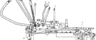
Rice. 3.41. 7G-Tronik gearbox design: 1 - drive shaft; 2 — torque converter locking clutch with torsional vibration damper; 3 — oil pump with pressure control; 4 — clutches and planetary gears; 5 - output shaft; 6 — parking brake; 7 - selector; 8 — electronic control unit; valves and sensors built into the pan; 9 — electronic gear shift unit; 10 - high-speed solenoids; 11 — torque converter
Since September 2003, Mercedes-Benz E, S, SL and CL class cars have been equipped with 7G-Tronik hydromechanical gearboxes (Fig. 3.40). This seven-speed automatic transmission replaced the five-speed GMT version. The new GMP made it possible to reduce fuel consumption by an average of 5%, depending on the car model. Gear changes are faster and smoother.
Gear shifting is carried out by three multi-disc brakes, which are acted upon by hydraulic cylinders. The pressure in the control system is created by a hydraulic pump driven by the engine through the torque converter pump wheel. To the bottom of the box
a hydraulic spool actuator is installed, which, using solenoid valves and at the command of the control unit, connects the hydraulic pump to the hydraulic elements of the clutch and brakes.
Rice. 3.42. Main elements of the electronic control system: 1 - control unit; 2 - connecting cable; 3 — control lever; 4 - electrical connector; 5 —GMP
The main elements of the electronic control system are the electronic unit and the control lever. In the right sector, the lever can occupy four positions:
P — parking mode;
R - reverse;
N - neutral gear;
D - driving in automatic gear shift mode.
When the lever is in position D, the program provides various switching algorithms in accordance with the driving resistance, load, gas pedal position, and road situation. Control algorithms correspond to movement in various conditions:
· movement at constant high speed;
· urban traffic mode;
· mountain driving mode;
· towing mode;
· driving around corners.
When the lever is moved to the left, the driver switches the gearbox to manual shift mode.
Move the lever back and forth to engage upshift and downshift. This gear shift is usually called sequential (sequential). The electronic control unit is adaptive; it remembers the driver’s driving style and adjusts the automatic gear shift algorithms.
Hydromechanical transmission (HMT) has been successfully used in cars for more than half a century and makes driving a car much easier.
The use of hydromechanical transmission in a car allows you to obtain the following advantages:
1. Ensuring automatic gear shifting and eliminating the need to have a clutch pedal.
2. Increased vehicle cross-country ability in off-road conditions due to the absence of interruption in the power flow when changing gears.
3. Increasing the durability of the engine and transmission units due to the ability of the torque converter to reduce dynamic loads.
At the same time, the disadvantage is the loss of power and increased fuel consumption due to the lower efficiency of the GMT compared to a car with a manual transmission.
The hydromechanical transmission includes three main parts:
torque converter;
manual transmission;
control system.
GMP first appeared on cars in the USA: in 1940, the Hydramatic gearbox was installed on Oldsmobile cars. To be fair, it should be noted that since the early 1930s, English buses have used a Wilson hydromechanical transmission, which was not automatic, but made the driver’s work easier. Currently, in the United States, 90% of passenger cars, as well as all city buses and a significant portion of trucks, are equipped with GMP. In Europe, the widespread use of GMT began only in the early seventies of the last century, when these transmissions found application in Mercedes-Benz, Opel, and BMW cars. At the same time, specialized factories for the production of hydrocarbons were being built in Europe: Borg-Warner was building a plant in England (Lethiford), Ford in Bordeaux (France), GM in Strasbourg (France). Two specialized production facilities appeared in Japan at once - Jatco and Aisin-Wamer.
The torque converter (Fig. 3.34; 3.35) was invented by the German professor Fettinger in 1905. Before being used on cars, the torque converter was used on ships and diesel locomotives.
The simplest torque converter is made in the form of a toroidal chamber and includes three bladed wheels: a pump wheel, the shaft of which is connected to the engine crankshaft; turbine, connected to the transmission, and a reactor installed in the torque converter housing (Fig. 3.36).
The torque converter is filled with a special fluid. Each wheel has outer and inner ends, between which there are profiled blades that form channels for fluid flow. All wheels of the torque converter are as close to each other as possible, and a special seal prevents fluid from leaking out.
When the engine crankshaft rotates, the pump wheel rotates, which moves the liquid between its blades. The fluid not only rotates relative to the axis of the torque converter, but also, due to the influence of centrifugal forces on it, moves along the blades of the pump wheel in the direction from inlet to outlet, which is accompanied by an increase in the kinetic energy of the flow. At the outlet of the pump wheel, the fluid flow enters the turbine wheel, exerting a force on its blades. The flow then enters the reactor, after which it returns to the entrance to the pump wheel. Thus, the liquid constantly moves through the flow parts of all three impellers. In this case, the pump transfers energy to the engine
If there were no reactor between the pump and turbine wheel, then such a design (fluid coupling) would transfer energy from the engine to the transmission hydraulically, without the possibility of changing torque
Rice. 3.36. Torque converter parts: 1 - pump wheel; 2 — turbine wheel; 3 — freewheel covers; 4 — part of the torque converter housing; 5—remains of working fluid with products of mechanical wear of parts; 6 — reactor wheel; 7 — reactor freewheel; 8 — turbine wheel thrust washer; 9 — thrust bearing of the reactor; 10 — torque converter locking piston
The maximum transformation ratio depends on the design of the torque converter and can be up to 2.4 (with a stationary turbine wheel). As the engine shaft rotation speed increases, the angular speed of the pump and turbine wheels increases, and the increase in torque in the torque converter gradually decreases. When the angular speed of the turbine wheel approaches the angular speed of the pump wheel, the flow of liquid entering the reactor blades changes its direction to the opposite.
To ensure that the reactor in this mode does not interfere with the fluid flow, it is installed on a freewheel, and it begins to rotate freely (the torque converter switches to fluid coupling mode), which, in turn, allows to reduce losses. Such torque converters are called complex ones.
The efficiency of a torque converter determines the efficiency of its operation. The maximum torque converter efficiency can range from 0.85 to 0.97, but is typically in the range of 0.7 to 0.8. In a complex torque converter in fluid coupling mode, you can obtain a maximum efficiency value of 0.97.
Changing the operating modes of the torque converter occurs automatically. If you increase the load at the outlet of the torque converter, the angular velocity of the turbine decreases, which leads to an increase in the transformation ratio.
Unfortunately, the torque converter has a small range of gear ratios, does not provide reverse movement, and does not disconnect the engine from the transmission (a complex system for emptying the flow parts from the working fluid is required). Therefore, a special gearbox is installed behind the torque converter, which compensates for these shortcomings. This hydromechanical transmission is continuously variable, allowing you to obtain any gear ratio in a given range.
Hydromechanical transmissions mainly use mechanical planetary gearboxes, which are easy to automate, but sometimes they also use conventional step-by-step gearboxes with automatic control.
A simple planetary gear consists of a gear and an outer gear in the form of a ring, with internal teeth; these two gears are connected to each other by means of several (usually three) satellite gears mounted on a common frame, which is called the carrier.
In order for a planetary gear to impart torque, it is necessary to ensure the rotation of one of its elements (the sun gear, ring gear or carrier), and to brake one of the elements. In this case, the third element will rotate with an angular velocity determined by the number of gear teeth included in the planetary gear. If you simultaneously brake two elements, the planetary gear will work like a straight line with a gear ratio equal to one. The planetary gear makes it easy to reverse the rotation to reverse the vehicle. At the same time, such transmissions are quite compact, provide the ability to obtain large gear ratios and are easily connected in series to obtain a large number of stages. To change gears, simply brake the shafts of individual elements of the planetary gearbox. Previously, band brakes were often used as braking devices, but recently they have been practically replaced by multi-disc “wet” clutches - friction clutches. There are also more complex versions of planetary gears.
The first American GMT passenger cars had a two-stage transmission, with the lowest gear being engaged manually. However, subsequently one auto-
Rice. 3.37. Simple planetary gear (a): A - sun wheel; B - epicycle; C - satellites; D - carrier; V—linear speed; and planetary gear diagram (b):
1 - sun gear; 2, 4, 6 — satellites; 3 - carrier; 5 - ring gear
Rice. 3.38. Options for planetary gears: 1, 2, 3 - shafts; 4 - carrier; 5, 8, 9 — satellites; 6, 7 — crown gear
automatic transmission was clearly not enough and GMTs with two and three automatic transmissions appeared. To increase fuel efficiency, torque converters began to be made locking - after acceleration in top gear, the pump and turbine wheels were rigidly connected by a friction clutch. Then in the late 1980s. Torque converter locking began to be used in all gears except first. An automatic control system usually consists of the following subsystems:
functioning (hydraulic pumps, pressure regulators);
measuring, collecting information about control parameters;
control, generating control signals;
executive, which controls gear shifting and engine operation;
manual control subsystem;
However, as before, much depends on the choice of the shift law and the organization of the transient process of gear shifting, as well as their careful coordination with the characteristics of the engine. dangerous situations. Late 80s. marked by the widespread introduction of electronics. It allows you to maintain specified switching moments much more accurately (with an accuracy of 1% instead of the previous 6-8%). Additional possibilities have appeared: based on the nature of the speed change at a given engine load, the computer can calculate the mass of the vehicle and introduce appropriate corrections into the switching algorithm. Electronic control provided unlimited opportunities for self-diagnosis, which made it possible to adjust control processes depending on the automatic protection subsystem, which prevents the occurrence of many parameters (from temperature and viscosity of the fluid to the degree of wear of friction elements).
| Rice. 3.39. Modern four-speed GMP of a classic car |
Rice. 3.40. Hydromechanical transmission 7G-Tronik - the world's first seven-speed automatic transmission (Mercedes-Benz)
However, as before, much depends on the choice of the switching law and the organization - the transient process of gear shifting, as well as careful coordination of them
with engine characteristics. For example, many BMW, Audi, Jaguar cars have automatic transmissions of the same design features from the same Zanradfabrik (ZF) company, but they work together
Rice. 3.41. 7G-Tronik gearbox design: 1 - drive shaft; 2 — torque converter locking clutch with torsional vibration damper; 3 — oil pump with pressure control; 4 — clutches and planetary gears; 5 - output shaft; 6 — parking brake; 7 - selector; 8 — electronic control unit; valves and sensors built into the pan; 9 — electronic gear shift unit; 10 - high-speed solenoids; 11 — torque converter
Since September 2003, Mercedes-Benz E, S, SL and CL class cars have been equipped with 7G-Tronik hydromechanical gearboxes (Fig. 3.40). This seven-speed automatic transmission replaced the five-speed GMT version. The new GMP made it possible to reduce fuel consumption by an average of 5%, depending on the car model. Gear changes are faster and smoother.
Gear shifting is carried out by three multi-disc brakes, which are acted upon by hydraulic cylinders. The pressure in the control system is created by a hydraulic pump driven by the engine through the torque converter pump wheel. To the bottom of the box
a hydraulic spool actuator is installed, which, using solenoid valves and at the command of the control unit, connects the hydraulic pump to the hydraulic elements of the clutch and brakes.
Rice. 3.42. Main elements of the electronic control system: 1 - control unit; 2 - connecting cable; 3 — control lever; 4 - electrical connector; 5 —GMP
The main elements of the electronic control system are the electronic unit and the control lever. In the right sector, the lever can occupy four positions:
P — parking mode;
R - reverse;
N - neutral gear;
D - driving in automatic gear shift mode.
When the lever is in position D, the program provides various switching algorithms in accordance with the driving resistance, load, gas pedal position, and road situation. Control algorithms correspond to movement in various conditions:
· movement at constant high speed;
· urban traffic mode;
· mountain driving mode;
· towing mode;
· driving around corners.
When the lever is moved to the left, the driver switches the gearbox to manual shift mode.
Move the lever back and forth to engage upshift and downshift. This gear shift is usually called sequential (sequential). The electronic control unit is adaptive; it remembers the driver’s driving style and adjusts the automatic gear shift algorithms.
About the torque converter
The heart of the type of box under consideration is a unit called a torque converter. Its device can be seen in the diagram:
The unit is located between the mechanical part of the gearbox and the engine, and serves as a clutch. The use of a torque converter allows, in addition to the convenience of the driver, to give the vehicle smooth starting and stopping, and to ensure movement without jerking. This directly affects the durability of the engine, since the dynamic loads that are inevitable when operating a car manually are significantly reduced.
Structurally, this unit is made up of disks with blades connected to each other:
Interesting: the entire disk unit is united by one casing, three-quarters immersed in transmission oil, which is the main operating medium of the automatic transmission.
The pump wheel rotates synchronously with the flywheel, at a similar speed. When rotation occurs, transmission oil flows to the turbine wheel, transmitting the rotational force to the latter. The oil then goes to the reactor wheel, which moves the liquid back to the original pump wheel. Thanks to the process of circulation of the working fluid under pressure, torque is transmitted to the wheels.
Interesting: the unit automatically determines the required gear ratio and transmits force to the automatic transmission, and the box already engages the desired gear using the clutches.
In addition to passenger vehicles, torque converters are used in heavy equipment: some models of shunting diesel locomotives and locomotives, diesel tractors, tractors, and cranes. A similar device drove the propellers of the tugboat Marshal Blucher. The Chaika, Volga, and ZIL cars equipped with a hydrodynamic transmission were also equipped with torque converters.
There are types of hydromechanical automatic transmission:
Torque converter device
You can understand what a hydromechanical transmission device is by studying its design. The main components are the torque converter, manual gearbox and control mechanisms. The torque converter is the main component, and it performs almost the same function as the clutch. Having studied the design of this part, you can see that it consists of three wheels that have a special shape. The first wheel is a pump wheel, its purpose is to communicate between the hydraulic unit and the power unit. The second ring is a turbine ring; it forms a connection with the input shaft of the box. The third wheel is a reactor wheel, its function is to increase torque. All three components are closed by means of a special housing, the internal volume of which is three-quarters filled with lubricant. From the engine, torque is supplied to the pump part, then, through rotational movements, it directs lubricant to the turbine wheel, as a result of which the force is transmitted to the input shaft. As the load increases, the torque converter will automatically change the torque, which in turn, transmitted to the mechanical components, will be switched through friction components. The fluid pressure passing from the pressure disk to the turbine is also regulated automatically.
Torque converter device
How does a shaft gearbox work?
Shaft automatic machines are quite widely used in the production of buses and heavy-duty vehicles. The word “shaft” refers to the manual transmission in an automatic transmission. The “mechanical” unit happens in this case:
To change gears, multi-plate clutches immersed in a special oil are used, and reverse gear, the first stage of the transmission, is in some cases engaged by a gear clutch. The design of such automatic transmissions allows you to switch speeds using clutches due to the operation of the crankshaft, without loss of power or loss of torque.
The classic design is two-shaft, with a primary (drive) and secondary (driven) shaft carrying gears. In the three-shaft scheme there is also an intermediate shaft, where the gear connected to the main gear is located.
Shaft models have found limited use in passenger cars: in particular, many Honda cars and a number of Mercedes models are equipped with them. The use of such gearboxes is associated with certain technical difficulties: on rear-wheel drive vehicles, an alignment requirement is applied to the gearbox, and the shaft automatic transmission must have at least two gears per gear. And this reduces efficiency.
Another disadvantage is high disk losses if the vehicle has more than three gears. In this case, there are many disengaged clutches in the shaft box, which leads to the indicated losses. In addition, the shafts are quite large in length, which makes the box bulky and reduces free space in the cabin, as well as increases noise and reduces reliability. This was partly solved by the introduction of three-shaft boxes, with shorter, stiffer and more reliable shafts.
Hydrostatic transmission
Hydrostatic transmission is a volumetric hydraulic drive.
In the presented video, a translational hydraulic motor is used as an output link. A hydrostatic transmission uses a hydraulic rotary motor, but the operating principle is still based on the law of hydraulic lever. In a hydrostatic rotary drive, working fluid is supplied from a pump to a motor.
Depending on the working volumes of hydraulic machines, the torque and speed of rotation of the shafts may change. A hydraulic transmission has all the advantages of a hydraulic drive: high transmitted power, the ability to implement large gear ratios, implement stepless control, and the ability to transfer power to moving, moving elements of the machine.
Control methods in hydrostatic transmission
The speed of the output shaft in a hydraulic transmission can be controlled by changing the volume of the working pump (volumetric control), or by installing a throttle or flow regulator (parallel and sequential throttle control). The illustration shows a closed-loop positive displacement hydraulic transmission.
Closed-loop hydraulic transmission
The hydraulic transmission can be implemented as a closed type (closed circuit), in which case the hydraulic system does not have a hydraulic tank connected to the atmosphere.
In closed-type hydraulic systems, the speed of rotation of the hydraulic motor shaft can be controlled by changing the displacement of the pump. Axial piston machines are most often used as pump motors in hydrostatic transmissions.
Open loop hydraulic transmission
An open hydraulic system is called a hydraulic system connected to a tank that communicates with the atmosphere, i.e. the pressure above the free surface of the working fluid in the tank is equal to atmospheric pressure. In open-type hydraulic transmissions it is possible to implement volumetric, parallel and sequential throttle control. The following illustration shows an open loop hydrostatic transmission.
Where are hydrostatic transmissions used?
Hydrostatic transmissions are used in machines and mechanisms where it is necessary to transmit large powers, create high torque on the output shaft, and carry out stepless speed control.
Hydrostatic transmissions are widely used in mobile and road construction equipment, excavators, bulldozers, and in railway transport - in diesel locomotives and track machines.
How does a planetary gearbox work?
For hydromechanical transmissions, manufacturers try to use a planetary mechanism:
In general, the design and operating principle of a hydromechanical gearbox created on the basis of a planetary system can be described as follows:
The carrier, when the ring gear is stationary, transmits force to the driven shaft; when it is released, the force goes through the satellites to gear number 2. The shaft itself remains motionless. Direct switching occurs through belt mechanisms and friction clutch packages.
Pros and cons of fluid mechanics
Summarizing what has been said, we can conclude: a hydromechanical automatic transmission is a unit consisting of a torque converter, a manual transmission module (in most cases planetary), equipped with a clutch pack, a hydraulic control system and a control electronic unit.
The advantages of this combination:
But there are also obvious disadvantages. One of them is relatively low efficiency compared to mechanics, which is due to the presence of a torque converter.
Important: during the circulation of the working fluid, part of the efficiency is lost: according to research, the efficiency of a manual transmission is about 98%, the same figure for an automatic transmission is in the range of 86-90%.
In addition, there are other disadvantages:
But the advantages of hydromechanical gear shifting still outweigh its disadvantages, especially for novice drivers who do not have sufficient experience. In addition, in the urban rhythm of traffic, with constant traffic jams, a hydromechanical automatic transmission saves both the strength and nerves of the driver, who does not have to perform endless “clutch-transmission” manipulations and drive at 1st speed with the clutch half depressed.
Source
Strengths and weaknesses of fluid mechanics
The hydromechanical gearbox is a series connection of a transformer, a planetary unit with the clutches of a hydraulic control system. Its main advantage is that the driver does not need to change gears manually. The electronics do this accurately, so there is no discomfort when moving, and the engine is not overloaded. Their absence helps to keep it intact for a long time. When starting to move, power transmission also occurs without interruption or jerking, which makes the hydraulic mechanics more advanced, surpassing in its characteristics mechanical gearboxes. It’s not for nothing that they are used not only in the automotive industry, but also installed on tanks (in America and Germany).
Important! If you are choosing a car in which you will mainly drive around the city, then you should choose a hydromechanical automatic transmission. With its help, you will not have any inconvenience when stopping in traffic jams or at traffic lights.
The weak part of such an automatic transmission is the torque converter
The disadvantage of this mechanism is its high cost and technical complexity. When changing gears, you may notice a loss of performance due to slipping of the clutches and brake bands. The weak part of such an automatic transmission is the torque converter, due to which torque is lost. Despite the obvious advantages, the efficiency of hydromechanics according to measurement results is 86%, while for a conventional box it reaches 98%. Another drawback is the need to install a hydraulic unit cooling make-up system. They take up space under the hood, which is why the engine and transmission compartment is large. Also, cars with installed hydromechanics cannot be started by pushing or moving it on a cable. This type of box, as with all automatic machines, is characterized by the inability to regulate fuel consumption. The described version of the hydromechanical automatic transmission is one of the most primitive. Today, more advanced transmissions are being developed and installed on passenger cars produced in recent years. It is recommended to use hydromechanics for those who have recently gotten behind the wheel. For a beginner, it is indispensable because there is no need to change gears yourself.