contents .. 1 2 3 6 ..
GAZ-66-11. Controls and instruments
The location of controls and instruments is shown in Fig. 3 and 4.
GAZ-66-11. Dashboard
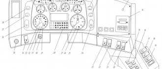
(see Fig. 4) is located on the instrument panel to the right of the steering column. It includes receiver 1 for engine oil pressure indicator, receiver 10 for engine coolant temperature indicator, receiver 11 for gasoline level indicator, speedometer 12 with a total distance meter, current indicator 13 and eight signaling devices (including reserve 8).
Emergency pressure indicator 3 lights up when the oil pressure in the engine is 0.4 ... 0.8 kgf/cm2. Indicator 2 lights up when the vehicle train identification lights are turned on. Indicator 4 lights up if one of the separate drive circuits fails the first time you press the brake pedal. Warning lamp 5 lights up when the high beam is turned on. Warning lamps 6 and 7 light up flashing when the turn signal is turned on. Indicator 9 lights up when the coolant temperature in the upper radiator tank is 104... 109 °C.
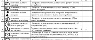
Rice. 3. Controls and instruments of the GAZ-66-11 car: 1—clutch pedal; 2—foot light switch; 3—indicator for switching on the lights of the identification sign of a road train; 4—plug socket; 5—button fuses; 6—switch for road train identification lights; 7—switch of the alarm system; 8— central light switch; 9—windshield wiper and washer switch; 10— turning headlight switch; 11—ignition and starter switch; 12—direction indicator switch; 13—gasoline level indicator sensor switch; 14—steering wheel; 15—instrument panel; 16—switch for checking the service brake system failure indicator; 17—brake system pressure gauge; 18—drive handle for the windshield blower damper; 19—air intake damper drive handle; 20—pressure gauge for tire pressure regulation system; 21— gear lever; 22—front axle activation lever; 23—transfer box gear shift lever; 24—switch of the magnetic valve and electric motor of the heater fan; 25—power take-off lever; 26—fuel tank switching valve; 27—battery switch; 28—button heater fuse; 29—heater spark plug switch; 30—handle for manual throttle control; 31—choke control handle; 32—cock handle for controlling the tire pressure regulation system; 33—parking brake handle; 34—radiator shutter control handle; 35—heater fan switch; 36—cabin light switch; 37 — throttle pedal; 38—brake pedal
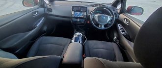
Rice. 4. Instrument panel
contents .. 1 2 3 6 ..
Features and diagrams of light direction indicators GAZ-66 and GAZ-53
The turn signal connection diagrams are shown in Fig. 1 and 2. The sidelights and rear lamp are switched on with a switch of type P105 on a GAZ-53A car and P118 on a GAZ-66 car. The operation of the switches is checked using test lamps according to the diagrams shown in Fig. 151 and 152.
In the off position, lamps 4 and 5 should light up. When the right turn is turned on, lamps 4 and 6, and when turning left, lamps 3 and 5.
If on a GAZ-53A car the switch does not turn off after the car exits a turn, adjust the position of the switch. To do this, loosen the two screws securing the switch to the bracket and move the switch until the rubber roller does not touch the steering wheel hub in the off position (there should be a gap of 2 - 2.5 mm).
When the switch is turned on, the roller should be firmly pressed against the wheel hub.
Every 25,000 km of vehicle mileage in the P105 switch, lubricate the roller axis, the lever axis and the lever plate that presses the roller. The direction indicators light up with a flashing light (70 - 100 flashes per minute). This is achieved by including a PC57 type breaker in the electrical circuit of the direction indicators.
Let's take a closer look at the design and operation of turn signal lights:
The most widely used are turn signal indicators with an electromagnetic-thermal current interrupter - RS57, RS57-V, designed for 12 V, and RS401 - for 21 V.
Turn signal device. A winding consisting of 50 turns of PEL wire with a diameter of 0.75 mm is placed on the steel core 9 (Fig. 3). The core is rigidly connected to bracket 11. The breaker winding is connected in series with warning lamps 16 or 17 located in the rear light and sidelight, and when using PC57 V, with warning lamp 12 located on the instrument panel in the driver's cabin. Steel anchors 4 and 10 are welded to the core
In the non-working state, contacts 5 are opened by the force of the stretched nichrome string 3, and contacts 6 are opened by the tension of the bronze plate 8. All contacts of the breaker are silver.
The lower end of string 3 passes through glass bead 2 and is thickened by fusing solder. The bead insulates the string from the bracket.
The resistor has a resistance value of 18 Ohms, made of nichrome conductor.
Normal operation of the RS57 breaker is ensured by simultaneously turning on two signal lamps of 21 light, and the RS57-B of two signal lamps of 32 light and one control lamp of 1 light. If one of the signal lamps burns out, the current strength decreases, as a result of which the blinking frequency of the lamps significantly increases, and in the circuit with the PC57 relay, the control lamp does not turn on.
Turn signal operation. When the signal lamps are turned on, the current from the battery will pass through the ignition switch 13, armature 4, string 3, resistor, winding, switch 15 and to the lamps (see Fig. 3). The current path in the diagram is indicated by arrows. The filament heat will be small.
The current passing through string 3 will cause it to heat up, as a result of which the string will lengthen and its tension will decrease.
At this time, the steel armature 4 will be attracted to the electromagnet core and the contacts 5 of the breaker will close. Closed contacts 5 bypass the resistor and string 3. The current strength in the lamps will increase and their filaments will glow with full incandescence.
Interruption of the current in the string is accompanied by its cooling and reduction in length. The string is stretched again and opens the contacts, after which the process is repeated. The vibration frequency of the contacts is 60 ÷ 120 openings per minute. Periodic closing and opening of the control lamp 12 circuit in the PC57 is ensured by the operation of contacts 6.
At the moment of closing contacts 5, the current strength in the electromagnet winding increases, so the core is magnetized more strongly and, attracting the steel armature 10, ensures the closure of contacts 6. In this case, the test lamp turns on at the full voltage of the current source and burns at full intensity. After contacts 5 open, due to a decrease in the current in the electromagnet winding, the magnetization of its core decreases, and then, under the action of the elastic bronze plate 8, contacts 6 open and turn off the control lamp circuit.
Controls and instruments of the GAZ-66 car
The location of controls and instruments of the GAZ-66 is shown in Fig.
5 and 6. The steering wheel 12 (Fig. 5) is located on the left side, in the center there is a horn button 15.
Rice. 5. Location of controls for the GAZ-66 car: 1 — clutch pedal; 2 — windshield washer pump pedal; 3 — foot light switch; 4 — plug socket; 5 — push-button fuses; 6 — fuel level indicator sensor switch; 7 - central light switch; 8 — direction indicator switch, 9 — turning headlight switch; 10 — ignition and starter switch; 11 — instrument panel ;
12 — steering wheel; 13 — air supply damper drive handle; 14 — tire pressure gauge; 15 — sound signal button; 16 — gear shift lever; 17 — front axle activation lever; 18 — transfer case lever; 19 — handle of the switch for the magnetic valve and the electric motor of the heater fan; 20 — power take-off lever; 21 — fuel tank switching valve; 22—mass switch; 23 — heater fuse button; 24 — heater spark plug switch, 25 — air damper handle; 26 — radiator shutter handle; 27 — throttle valve control handle, 28 — tire pressure control valve handle; 29 — handbrake handle; 30 — heater switch; 31 — cabin light switch; 32 — throttle pedal; 33 - brake pedal Brake pedal 33, clutch pedal 1 and throttle pedal 32 are placed in accordance with generally accepted standards.
Foot light switch 3 and windshield washer pedal 2 are located on the left side of the cab floor. By pressing the foot light switch button, depending on the position of the central light switch, low beam can be turned on instead of sidelights or high beam instead of low beam, and vice versa.
To wash the glass, turn on the windshield wiper and press pedal 2 until the glass is clean.
The socket 4 and three push-button fuses 5 are installed on the left side of the cab on the rack.
To the right of the driver is the gear shift lever 16. Lever 17 for engaging the front axle and lever 18 for the transfer case are located to the left of the gear shift lever, lever 20 of the power take-off is on the right.
Source
Controls and instruments
The location of controls and instruments is shown in Fig. 1 and 3. Steering wheel 14 (Fig. 1) is located on the left side. There is a horn button in the center of the steering wheel. The brake pedal 38, the clutch pedal 1 and the throttle pedal 37 are arranged in accordance with the generally accepted standard. On the floor of the cabin on the left side there is a foot light switch 2. By pressing the foot light switch button, you can switch from high beam to low beam and vice versa in the third position of the central light switch. On the left side of the cab, on the front pillar, there is a plug socket 4 and three push-button fuses 5. On the bracket under the instrument panel there is an indicator 3 and a switch 6 for the road train identification lights. When operating a vehicle with a trailer, the lights are turned on, as indicated by the indicator. To the right of the driver is the gear lever 21. Levers 22 and 23 for controlling the transfer case are located to the left of the gearbox lever, lever 25 for controlling the power take-off is on the right. The layout of the levers is shown in Fig. 2. On the top panel of the hood there are bolts for fastening the NVD device brackets. The central light switch 7 is located on the instrument panel (see Fig. 1). The switch has three positions:
2. Instrument lights, front lights, rear license plate lights and tail lights are on.
3. The instrument panel lights, headlights, low beam or high beam headlights (depending on the position of the foot switch), rear license plate lights and tail lights are on.
By rotating the switch knob, you can adjust the intensity of the lighting of the devices.
Switch 8 alarm. When the position is on, all four turn signal lamps and the indicator light (red) inside the switch handle light up simultaneously in flashing mode.
The hazard warning lights must be turned on when a vehicle is forced to stop on the roadway in order to notify drivers of other vehicles and provide information to technical services about the presence of a stationary vehicle on the road. Switch 9 for windshield wiper and washer. Turning the switch knob clockwise turns on: in the first position, low speed, in the second, high speed of the windshield wiper. In all positions of the switch, including the off position, when you press the switch handle, the electric washer and windshield wiper operate simultaneously. Switching off occurs via a return spring after the switch handle is released. Turning headlight switch 10. Switch // ignition and starter. It has three key positions: 1 all off, 2 ignition on, 3 ignition and starter on. Switch 12 direction indicators. When the turn indicators are turned on, the warning light on the instrument panel should light up. The absence of a flashing light indicates a malfunction or a burnt-out filament in the front or rear turn signal lamps. Switch 13 gasoline level indicator sensors. Switch 16 for checking the malfunction indicators of the hydraulic drive of the service brake system and the air pressure in the receiver. When the switch is turned on, the corresponding ones light up; signaling devices, if their lamps are working. Pressure gauge 17 for monitoring the pressure in the receiver. Handle 18 for the windshield blower damper drive and handle 19 for the air inlet damper drive. Pressure gauge 20 for monitoring tire pressure. Handle 34 for radiator shutter drive. To cover the blinds, pull the handle up. Cabin heater fan switch 35. Switch 36 of the cabin lamp. On the removable floor of the cabin there is a handle 24 for switching the magnetic valve and the electric fan motor. Three-way valve 26 for switching the gas tank. Battery switch 27. It has two buttons: for off (under the safety bracket) and on (on top of the switch). Push-button fuse 28 of the control panel. Switch 29 of the heater plug. Handle 30 for manual control of the throttle valves. Pulling the handle opens the carburetor throttle valves. Handle 31 for controlling the air damper. When you pull it up, the carburetor air damper closes. Handle 32 of the valve for controlling the tire pressure regulation system. Handle 33 for parking brake control. To brake the car, pull the handle up.