The crank mechanism of the T-25 tractor (Figure 1) perceives through the pistons (item 9) and connecting rods (item 6) the gas pressure that occurs during the combustion of diesel fuel in the cylinders of the D-21 diesel engine , and converts the rectilinear movement of the piston into rotational movement crankshaft (pos. 17) of the engine. To ensure durable and reliable operation of the engine, the components of the crank mechanism are manufactured with a high level of precision and from high-quality materials.
The pistons (item 9) are cast from aluminum alloy. At the bottom of the piston there is a spherical combustion chamber. The outer surface of the piston has five grooves for installing rings (items 7, 8): the top three grooves are for compression rings, the bottom two are for oil scraper rings. In the grooves for the oil scraper rings, as well as on the cone-shaped surface under the grooves, holes are drilled to drain the oil, which is removed from the surface of the cylinder. The connecting rods (item 6) are made of chrome steel. At the ends of the connecting rod rods there are upper and lower heads. A bronze bushing is pressed into the upper head. The head and bushing have a hole through which lubricant is supplied to the piston pin.
The lower head cover is attached to the connecting rod using two special bolts and nuts. Relative to the connecting rod, the bolt is secured against turning by the flat edge of the head. The crankshaft (item 17) is supported by three main bearings. The shaft is made of chrome steel. The connecting rod journals are rotated 180° relative to each other. Two oil channels are drilled from the first crankpin, one of which goes to the first main journal, and the second through the second main journal to the second crankpin. Inclined channels are plugged with conical plugs.
At the front end of the crankshaft there is an oil slinger, a distribution drive gear (item 4), an oil pump drive gear (item 3), and a pulley (item 1). A flywheel (pos. 12) is mounted at the rear end of the shaft. The crankshaft of the D-21 engine has four counterweights (item 19), which are bolted to the cheeks. At the front end of the crankshaft there is a threaded hole designed for a special fan pulley tightening bolt.
Balancing of the crankshaft of the T-25 tractor is carried out dynamically, with assembled counterweights. The shaft is balanced by drilling metal counterweights in places specially provided for this. From axial displacements, the crankshaft is fixed in the block by the second main journal. The rear end of the crankshaft is made with a boring for the front bearing of the clutch shaft. In order to prevent lubricant from leaking out of the bearing, a frame self-clamping oil seal (pos. 13) is immediately installed.
The flywheel (item 12) is cast from gray cast iron. Increases the uniformity of diesel operation and also transmits torque to the transmission of the unit through the clutch. The flywheel is made with a bore and six holes for mounting bolts, as well as two holes for the crankshaft dowel pins, which are necessary for centering. The clutch disc is pressed against the flywheel surface. The end of the flywheel has six threaded holes and two smooth ones, which are necessary for attaching and installing the clutch housing.
The conical surface of the flywheel has two drilled inclined holes through which oil drains when it enters the flywheel from a diesel engine or from the transmission housing. The flywheel crown is made of steel and pressed onto the flywheel with tension. Before pressing, the crown is heated to a temperature of 280–300°. The number of crown teeth is 133. The crown teeth are hardened by high-frequency currents.
Electrical diagram of Tractor T-25
The machine uses a single-wire wiring system that produces a voltage of 12 V. A metal case is used as ground. The electrical system is equipped with sensors that provide information to the driver’s cabin about:
- oil pressure and temperature;
- voltage in the electrical system;
- speed and so on.
A distinctive feature of the T-25 tractors was the presence of heating in the driver’s cabin, which was started from the hydraulic system. In more modern modifications, the heater was started from the engine lubrication system. The idea was good, but it turned out to be ill-conceived. The heater did not work very well due to the fact that the large hydraulic tank was located outside the tractor and the heat did not flow into the cab.
This annoying drawback can be easily eliminated by installing an additional tube with a two-position valve, which connects the hydraulic lift system tank to the radiator outlet.
Modern modifications of tractors, created on the basis of the T-25, are equipped with more powerful engines, hydrostatic steering, all-wheel drive and a comfortable operator’s cabin.
content .. 1 2 3 9 ..Chapter II
ENGINE D-21 OF TRACTOR T-25: GENERAL DEVICE
Engine - diesel, 4-tant, uncompressor, air-cooled with direct fuel injection.
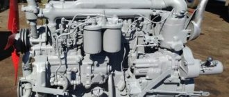
The D-21 engine is a two-cylinder model of a family of air-cooled diesel engines, developed by the Vladimir Tractor Plant. Engines of this family can be two-, three-, four- and six-cylinder. These engines have unified parts of the crank mechanism (piston, connecting rod, piston rings, connecting rod and main bearings), all parts of the gas distribution mechanism (except for the camshaft), cylinders and cylinder heads. General views of the D-21 engine are shown in Fig. 4, 5, 6, 7 and 8.
D-21 engines are also installed on the T-16M self-propelled tractor chassis and on a number of other machines.
All units, components and mechanisms of the engine are mounted directly on the crankcase, flywheel housing and timing gear cover.
The D-21 engine is designed as follows. On the left side along the tractor (Fig. 4) there are fuel equipment 6, inlet and outlet 4 pipelines, a middle deflector 5 and a glow plug 8 in the suction pipeline. On the front part of the engine (Fig. 5) there is an oil filler neck, an axial fan 1 with a built-in generator, the guide vane of which is fixed to the distribution cover with a band clamp, an hour meter, a jet centrifuge 4, coarse and fine fuel filters 2, an oil dipstick 5, fan and generator drive pulley with marks TDC (top dead center), BDC (bottom dead center) and T (start of fuel supply by the pump). On the right side there is a decompressor drive mechanism, starter 2 (Fig. 6), nozzles and fan casing 3. On the rear side of the engine, the flywheel housing is attached directly to the crankcase.
Rice. 4. Engine D-21 (left view): 1- hour meter; 2 - centrifuge; 3 - fuel filters; 4 — exhaust pipeline; 5 - middle deflector; c - fuel pump; 7 - flywheel; 8 - glow plug.
Rice. 5. D-21 engine (front view): 1 - fan; d — fuel filters; 3 - glow plug; 4 - centrifuge; 5 - oil dipstick; c - plug.
The working cycle of the D-21 diesel engine consists of the following strokes: intake, compression, power stroke, exhaust.
During the intake stroke, the piston moves from top to bottom dead center, while the intake valve is open and clean air is drawn into the engine cylinder through the air cleaner and the intake manifold. During the compression stroke, the piston moves from bottom to top dead center and the intake and exhaust valves are closed. The air entering the cylinder is compressed to 42 atm. and its temperature rises to 650-700 °. At the end of the compression stroke, 22-24 0 (according to the angle of rotation of the crankshaft) before the piston reaches top dead center in the combustion chamber under
Finely atomized fuel is injected at a pressure of 170–175 am. The temperature in the combustion chamber reaches 1750 °, and the pressure increases to 72 am. Under the influence of this pressure, the piston moves to the bottom dead center, and thus the power stroke occurs. The valves are closed during the working stroke.
During the exhaust stroke, the piston moves again to top dead center and through the open exhaust valve pushes the exhaust gases out of the cylinder and cleans the cylinder.
With further rotation of the crankshaft, all strokes are repeated in the same sequence. The operating order of the cylinders is 1—2—0—0. Due to the fact that the crankshaft elbows are placed at 180° relative to each other, the power stroke in the 2nd cylinder always occurs 180° after the power stroke in the 1st cylinder, i.e., two power strokes are made in a row in the engine. Then this cycle is repeated after 540°, i.e. the working stroke in the 1st cylinder occurs 540° after the working stroke in the 2nd cylinder. This causes uneven rotation of the engine crankshaft, which is reduced to a large extent with the help of a flywheel whose weight is specially selected.
During engine operation, forces arise in the crank mechanism from gas pressure and the inertia of the moving masses of the crank mechanism, friction force and useful resistance on the engine shaft.
Inertial forces are divided into inertial forces of masses moving back and forth, and inertial forces of masses moving rotationally.
The forces from the gas pressure in the engine cylinders manifest themselves in the form of torque on the engine crankshaft and a moment that tilts the engine, which is perceived by the engine mounts and transmitted to the tractor frame. The tipping moment is equal in magnitude to the torque on the engine crankshaft and is directed in the opposite direction.
The inertial forces of masses moving back and forth manifest themselves in the form of two moments - torque and tilting and free force acting along the cylinder axis, which is perceived by the engine mounts.
Half turn
geniculate
shaft
| Crankshaft angle (degrees) | Cylinder | ||
| 1st | 2nd | ||
| 1st | 180 | Working stroke | Compression |
| 2nd | 360 | Release | Working stroke |
| 3rd | 540 | Inlet | Release |
| 4th | 720 | Compression | Inlet |
The inertial forces of masses moving rotationally manifest themselves in the form of a centrifugal force, constant in magnitude, directed along the radius of the crankshaft crank and applied at the center of the connecting rod journal. Centrifugal forces are transmitted through the main bearings to the crankcase and are then received through the engine mounts by the tractor frame. The engine will be balanced if, under steady-state operation, a constant force in direction and magnitude acts on the engine mounts and through them on the tractor frame.
During engine operation, the balancing mechanism creates forces equal in magnitude and opposite in direction to unbalanced forces, which reduces their harmful effects.
Rice. 6. Engine D-21 (right view): 1 - crankcase engines: 2 - starter; 3 — fan casing; 4 — fan mounting clamp; 5 - pressure reducing valve; 6 - oil pan.
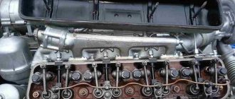
Rice. 7. Longitudinal section of the D-21 engine; 1 - oil pump; 2 — connecting rod, 3 — fan; 4 - fan; 5 — cylinder head; 6 - valve; 7 — ground floor 8 — flywheel; 9 - crankshaft,
Rice. 8. Cross section of the D-21 engine: 1 - oil receiver; 2 - starter; 3 — fan casing; 4 — inlet pipeline; 5 - glow plug; 6 — exhaust pipeline; 7 - cylinder; 8 — crankcase; 9 — roller of the balancing mechanism; 10 - plug,
content .. 1 2 3 9 ..
T-25 capabilities
The design of the T-25 allows you to adapt the vehicle to specific needs. For example, changing the track width, which allows you to work on any fields and farms. Changing the agrotechnical clearance will allow the tractor to be used on slopes.
The tractor can move during operation both in reverse and forward. It is also possible to set up the machine for long-term operation in reverse. The drive pulley installed on the T-25 opens up the possibility of connecting stationary equipment and machines. An additional brake cylinder will allow the use of a semi-trailer.
Lubrication system T-25
The T-25 tractor uses a D-2 diesel engine, which uses a combined lubrication system. This means that the main part of the mechanisms and parts are lubricated under internal pressure in the system and splashing oil.
Operating principle and diagram of the tractor lubrication system
To begin with, we present a diagram of the general tractor lubrication system.
A T-25 oil pump is installed at the bottom of the sheet, which ensures complete oil circulation in the engine. We described it in detail in one of our articles, but let us remind you a little. That the pump is driven by the crankshaft using two gears. Its performance depends directly on the rotation of the crankshaft. And at a speed of 1400 rpm it is 12 liters/hour.
An oil pump mounted on the bottom of the front sheet circulates oil through the engine. The pump operates from the crankshaft drive using two gears: a driven one mounted on the drive shaft of the oil pump, and a drive gear pressed onto the crankshaft.
The minimum pressure that should be in the system at idle is 1.5 kg/cm².
If it is more than 3.5 kg/cm², then there is a very high probability of its breakdown and leaks in the connecting pipes; if it is less than 1 kg/cm², then the system will not be sufficiently lubricated and will quickly fail. Therefore, it is imperative to monitor your blood pressure. This can be done using a pressure gauge (3).
A pressure reducing valve is installed on the left side of the cylinder block; it is responsible for controlling and maintaining constant pressure in the system; we provide a diagram of the pressure reducing valve of the T-25 tractor below.
To clean the system from various mechanical impurities and various products that appear during natural wear, an oil filter is used - a centrifuge, which is installed on the cover of the timing gears.
The nominal oil volume in the system is 7 liters.
The oil in the system can be of different standards, which determines the frequency of maintenance and replacement.
Overall dimensions of the T-25 tractor
The variable characteristics of the tractor also affected its overall dimensions. The length of the tractor with a load and hydraulic attachment system when installing 9.5/32 wheels will be 3110 mm. If you install 10.00/28 tires on the vehicle, the length will be 3098 mm.
The width of the T-25 with 9.5/32 tires with a minimum track will be 1370 mm. If you install 10.00/28 tires, the minimum track width will reach 1467 mm. The height of the T-25 in any type of cab with 9.5/38 tires is 2500 mm. With 10.00/28 tires the height will be 2488 mm.
The track width of the front wheels is adjustable within the range of 1200-1400 mm every 10 cm. The track width of the rear wheels with 9.5/32 tires is adjustable within the range of 1100-1500 mm, with tires 10.00/28 - within the range of 1200-1480 mm.
The agrotechnical clearance measured under the brake hoses will be with a high lining:
- using tires 9.5/32 - 657 mm;
- with installation of tires 10.00/28 - 645 mm.
With average pad the ground clearance is:
- with installation of tires 9.5/32 - 587 mm;
- with installation of tires 10.00/28 - 575 mm.
With a low trim, the ground clearance will change to:
- 450 mm - with 9.5/32 tires;
- 438 mm - with 10.00/28 tires.
The structural weight of the T-25 (without cargo and fuel) will be 1780+50 kg when installing 9.5/32 tires, and 1820+50 kg when installing 10.00/28 tires.
The operating weight of the tractor, ready for use, will be 2020+50 kg with 9.5/32 tires and 2060+50 kg with 10.00/28 tires.
Rice. 1 — Crank mechanism of the D-21 diesel engine of the T-25 tractor
1 — fan and generator drive pulley D21A-1308157-A; 2 — special bolt (ratchet) D37M-1005146; 3 — drive gear of the oil pump D144-1403312; 4 — drive gear of the distributor D30-1006285-A2; 5 — connecting rod bearing shell; 6 — connecting rod D37M-1004100-A2; 7 — oil scraper rings; 8 — compression rings; 9 — piston D21-1004021-A2; 10 — upper thrust half-ring; 11 — main bearing shell; 12 — flywheel with crown D21-1005300-A; 13 — self-clamping oil seal 1-20x40-1; 14 — bearing 1204; 15 — main bearing shell; 16 — connecting rod bolt nut; 17 — crankshaft of the D21-1005007 engine; 18 — lower thrust half-ring; 19 - counterweight.
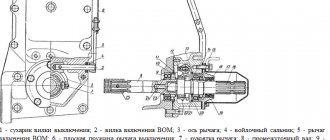
The balancing mechanism of the D-21 engine (Figure 2) includes a roller (item 3), front (item 1) and rear (item 4) weights, a drive gear (item 2) and fastening parts on the weight roller. The roller (item 3) is located in the block bores. Bronze bushings, which are bearings, are pressed into these bores. The drive gear is pressed onto the shaft and is held from turning by a segment key. The front and rear weights are mounted on the ends of the roller (item 3), secured with bolts and washers and secured against rotation with segment keys. For the drive gear and weights, the keys are interchangeable. The mechanism shaft and weights are made of steel.