Hydraulic systems are machines and tools that use fluid power to do work. Almost all types of hydraulic equipment are a typical example. With this type of equipment, hydraulic fluid is pumped at high pressure and transmitted through various drives.
Hydraulic pumps are driven mechanically or by an electric motor. The fluid pressure is controlled by a control valve and then distributed through hoses and tubes. The growing popularity of hydraulic systems is due to the large amount of energy that is transferred through small tubes and flexible hoses. High power density and a wide range of drives make the use of hydraulic machines popular.
Hydraulic system of the T-25 tractor
Pumps.
The hydraulic pump supplies fluid to the system components. The pressure in the system will develop in response to loads. Pumps have a power density of about ten times that of an electric motor. The pumps are designed to be driven by an electric motor or mechanical drive, which is connected through transmissions, belts, or a flexible flexible coupling to reduce severe vibration.
Common types of hydraulic pumps include applications: Gear Pump - A gear pump is cheap, durable, and simple. This is less efficient simply because this bias constant is suitable for pressures that are below 3000 psi. Vane Pump - Vane pumps are cheap, simple, and reliable. They are good for systems with low flow at low pressure outlet.
This article contains questions and answers from people who encountered problems when repairing the T-25 tractor.
How to reduce play on the steering column of the T25 tractor?
On the right side of the hydraulic distributor at the bottom of the steering wheel there is a nut, unscrew it, there is an adjusting screw usually for a screwdriver, so we turn it clockwise, to eliminate the play you need to move the worm closer to the shaft, also look at the bipod shaft bushing, if there is play, change the bushing , check the front axle balancer, there is movement, change the bushing. We check the steering rods, there is play, we change the end bearings, use the adjusting bolt to move the roller relative to the worm to the right or left, tighten the adjusting bolt with a nut, the result is positive, if not, the steering rod fingers are broken.
Final drive crunching?
The final drive has roller bearings. If they are crushed, the wheel may fall off along with the axle shaft and even break the axle shaft. This usually happens on a wide track, set the track to 1400mm, the problem disappears.
Valve clearance t-25. Is it possible to adjust the sprayer injection on site?
We install 0.3 intake and exhaust valves, injection stand only.
We adjust the reverse so that it does not hum.
The reverse is adjusted using repair washers (thin plaques). When the reverse is assembled, take a sheet of newspaper and insert it between the gear teeth. When turning the reverse, the gear teeth should not cut the newspaper.
We are installing an additional hydraulic tank, are additional modifications required?
There are no improvements. We drain the additional tank into the filler neck of the original tank, and that’s all the modifications. We drill the filler plug, insert the fitting onto the thread, and put on the hose.
Will there be pressure on the oil filter?
There will be no pressure on the filter, there will be a hose with additional. tank in the original tank in the filler neck, the excess will be drained into the additional tank. tank through this hose.
We knock out the steering knuckle bushings.
We place the beam on a rigid stand, take an extension, preferably one that goes inside the body of the beam. We take a good hammer and knock out the bushing with strong and sharp blows. It is important that the beam does not vibrate, if it does not move, soak a rag in kerosene and place it on top for a day, knock it out, if that doesn’t help, heat it with a blowtorch and knock it out carefully, but firmly so as not to flare the edges of the beam.
Piston for PD-8 launcher.
The piston from Izh Planet fits on the PD10, on the PD8 it fits from the Tula scooter, it’s better from a truck, the piston has 3 compression rings and it will be better to start. There is a piston on the “ant”, with PD 8, since sunrise the piston will not fit a finger smaller in diameter
Power steering for T-25.
We take a longitudinal rod with a dispenser from a GAZ 66 car. We cut off our rod, cut rod 66, measure it and weld it. Gur from 66, put the pulley in two streams. We take a pulley from a T-40 tractor and install a cylinder also from 66.
I installed a pulley from a T-40 and the tractor began to tremble, it turned out that the pulley was not balanced. I connected from the pump to the dispenser, the return to the distributor works not bad, but there is one thing. When lifting the hitch, it sometimes throws to the left. And so everything is fine with one finger.
Install a T16 steering wheel and don’t worry. I used to suffer too. then he spat and remade it.
I rebuilt the steering from T16, installed an NSh 10 pump, placed it above the generator, driven by a belt drive.
We change brake bands.
Disassemble one part of the tape that you will be changing completely, flatten the ear a little, hook it with a thin cable, and run the cable under the drum. The wheel is jacked up, pull the cable and spin the wheel. After removal, make sure the tape is dry. If the band is oily, replace the seals immediately, otherwise even new brake bands will work very poorly.
My brother changed it, removed the top cover, pulled the tape with a wire and pulled it out with a crowbar. Then he wound the wire under the drum, inserted the tape as far as he could, and, pulling the wire, inserted the tape into place.
We change the rear tires to wide ones.
Rear tires of the Don -1500 combine; size 18.4×24, assembled with disks on both T-25 and T-16. I don't remember the model; 4 layers of cord. Put it in, you won’t regret the speed, air suspension and cross-country ability. The disadvantages are that it is maneuverable and the door on the cab must be closed when moving backwards.
We are replacing the power steering pump.
I installed a three-section distributor on my tractor; one section is not fully engaged, it only works in two positions, lowering and floating, and it’s very convenient for me with my hand on the lever, down, lift, floating, and up neutral. There is probably only one option for NSh 32; it probably needs to be installed only forward on the crankshaft, through the cardan. You can go to the same place where the original one is, only the gearbox needs to be changed, and there is no place to put it in front. I have an NSh-10 on the front end with a belt drive. With T16, the steering column was installed with a hydraulic steering much simpler.
The wheel lock is stuck.
The box is removed in one block with the rear axle, if desired, the whole box can be disassembled on site, and I also had a tractor with a homemade cabin, so I don’t know if the floor of the cabin is completely removed, can you remove the cover without removing the cabin and crawl up to blocking?
We remove the cabin assembly, remove the box cover, but here you will have to tinker with the brake shafts, they will not allow you to remove the cover. If the shafts have not been removed, this may not be so easy. If the clutch is stuck, you may have to disassemble the entire left final drive. If you remove the cover, cut it with a grinder in the area of the clutch shaft; in the future, when repairing the box, you do not need to remove the cabin.
What about the brake shafts? what to do if they have never sorted it out?
The shafts in the cover are locked with pins; sometimes the pins are very difficult to pull out. They are small and sometimes they fit tightly, depending on how it goes. And if you drove a tractor with the locking switched on, could the gears be cut? If the gear is not cut, it often breaks off the bolts that secure the gear to the cup. If the bolts are loosened, a dull knock appears when starting off, regardless of whether the lock is engaged or not. Even if you have a problem with the load release mechanism, the clutch would be thrown out anyway. It happens that under load you hold it with your foot and feel how the clutch is knocked out, apparently, the clutch and gear are bitten and, moreover, tightly
How can I disengage it after I open the box?
In this case, opening the box will not help; you will need to completely remove the left side. If the problem is in the locking gear, it will be necessary to remove the differential, and for this it is necessary to remove the right side one. In general, replacement requires complete disassembly of the main gear. I've had similar repairs. There was a case where the unusable locking gear was completely cut off, and the tractor was operated without any locking at all; in another case, a differential was installed with dt 20, which is not there from the factory. Tractors still operate without blocking.
What could be wrong with the fuel pump, they replaced my high pressure section, now the engine starts with difficulty and the exhaust has become loud?
I suffered for almost a month. Then I found the reason, it turned out that I had installed a new high-pressure tube, and it was defective and did not allow all the diesel to pass through.
d-21 “reducing valve” what role does it perform? Is the valve adjustable?
It regulates the pressure in the engine, you can adjust the desired pressure. What pressure should be in the engine? How is it regulated? On cold 4, on hot 3, wrap it a little and try. Adjust when cold or warm? Doesn't matter.
The valve limits the maximum pressure of a cold engine. Adjustable at cold 3.5. If a normal engine at 80 degrees will hold 3. If not, then even 4 when cold will not help.
Which flywheel is suitable for the T-25 engine? Non-standard assembly. Engine D-21, basket, release, gas box 52.
I want to attach a gas 52 basket and a box to d-21. Welded bell from a wheel disc or pipe. I can’t find it for the D21 engine. They say they are different.
For my T-40 engine, a large circle is cut out onto the block; it is cut out from a Kirov part; it is somewhere in the gap near the tractor, and a bell from GAZ-53 is screwed onto this circle; the rest is a clutch from GAZ-52 and a gearbox from GAZ-52 Flywheel It is not advisable to depersonalize the crankshaft during repairs; there is no guarantee of balancing. But ideally, the D-21 flywheel is bored out so that the GAZ-52 basket fits in, and secured. The GAZ-52 basket is technically not very interesting.
When installing another flywheel, vibration may occur (I experienced it myself). I have a T-25, a T-16, a relative made a homemade D-21 engine, a GAZ-52 clutch, a GAZ-53 gearbox, a GAZ-66 transfer case, a cut-down GAZ-51 axle. A hole is bored in the flywheel into which the GAZ-52 basket fits, a thread is cut, and screwed with the same bolts.
I don't like the basket because of the suspension of the legs and their adjustment. I plan to insert the GAZ-53 disk into the bored hole, the pressure disk of the GAZ-53 basket will fit, I will cut off the basket casing, insert it into the hole on top of the basket, and weld plates to attach it to the top of the hole. Or I will fit the T-25 clutch into the bored hole of the flywheel onto the GAZ-53 disc.
The GAZ-52 disc should fit into the unbored flywheel and take the T-25 clutch, but the arms will need to be lengthened. Make the clutch cover from the brake drum (front) ZIL-130. And see how much to lengthen the input shaft of the box that will be installed.
Which bearing is better to install on the primary tapered shaft 308 regular or 308 thrust?
The usual 308 is installed. The thrust load is held by the next bearing on this shaft 306. Under serious loads, my Soviet bearings withstood 10 years.
The native one is simple, just put it like that, there is no need for stubborn ones there. Factory, regular, lasts forever! During the operation of tractors such as the T-25, I have never encountered such a problem! Why reinvent the wheel?
Who made a homemade kun on the T-25? If so, how were they attached to the spars?
On the T-25 I made something like a haystack shooter, it raises the boom by 3.7. in general it doesn't matter. You make new spars, that is, you remove your own. Place two corners on the stove lengthwise. Angle 150, weld another one fifteen centimeters longer across it, put a square pipe on top of this base, I put a channel. I secured it to the stockings where the cabin is attached.
What kind of work are you going to do? I mainly use my tractor to prepare hay. My steering wheel is mechanical, so I don’t put much load on the front end, and the front end is rather weak. And if you carry out work on a grand scale, then it’s better that MTZ will withstand any work right away. For the T-25, even 3.7 lift is quite enough, it’s even scary when you’re working at the full reach of the boom. The tractor is good, but it is light and narrow, there is a risk of tipping over. In general, there is such a risk.
Cylinder 2 D-21 does not work; I swapped the injectors, maybe the fuel injection pump? Although you brought it back from repairs, worked for a bit and stopped, it’s not picking up speed well?
Try and look at the timing mechanism. And the injectors may be set to a higher pressure than the injection pump produces. On such an engine, I set the pressure for the injectors to 165 atm. Most likely it's the pump, no power!
What compressor can be made on the T-25 or from what tractor can it be installed?
I installed it from the T-40. It is not always needed and cannot be disabled. It does take a little bit of precious power from the engine. Fuel consumption increases. The fuel injection pump drive gears are more loaded.
The low and high beam bulbs burn out, what is the reason? Change the integral in the generator.
Who recommends what kind of oil to put into the engine?
Try 15w40, if you feel the technique, you will notice the difference immediately!
Tell me why the hydraulics cannot lift the tractor. The plow lifts normally, but cannot lift itself.
He shouldn't lift himself! The pressure in the hydraulic system is limited by the spool valve - 120 atmospheres. When this pressure is reached, the lever automatically switches to the neutral position. If you hold the lever in the lift position, then when you reach 140 atm. the safety valve opens. Hydraulics cannot provide more force!
It all depends on where the force is applied. The shorter the lever, the greater the lifting capacity. In any case, there is a limitation - the operation of the distributor safety valve!
The clutch pedal does not move back halfway. What is the possible reason? You play with speeds, sometimes it goes away.
Open the hatch and look at the retaining balls. Perhaps they have soured. Adjust the speed locking mechanism.
What is this bolt for, and for this crane, if it is in the wrong position, it may not lift?
This is not a bolt, it is an oil level control plug in the NSh-10 drive. And the top arrow points to the stove throttle, i.e. Because of this throttle (according to the designer’s intention), the oil in the system should be heated and the stove should be heated, in fact it’s complete nonsense! If the pump is running low and weak, then because of this the throttle may not lift in the summer, there are 2 positions Winter and Summer, in the summer it should be on L. This whole system is removed and not bothered, and the stove is made on a muffler.
I have such a situation that the pump only rises when you give it gas and then jerkily?
What kind of oil is in there? And how is it available? Does it lift what, a hitch or a body on a cart? First, there is not enough oil, the hydraulic system filter is clogged, the oil is not filled with motor oil, but I20 or I40, although the pump is good and works fine on it, then the pump is finished! The valve in the distributor may be leaking.
Check the pump and the presence of oil in the hydraulic tank! It looks like your valve in the hydraulic distributor is stuck, or something got under it, so it won't hold. If everything is fine with this and you haven’t found the problem, then look at the cylinder itself, the piston may be bypassing! Maybe the nut on the cylinder will unscrew and bypass, and the linkage itself will lower.
Replaced the high pressure section ND 21/2. The ignition set correctly and the throttle response is normal. But when loaded it smokes black smoke. I turn it down with the corrector body (I don’t twist it too much) and it doesn’t pick up speed?
That's it, I figured it out! There, in the regulator, some smart guy put a very stiff spring, not his original one. Now, out of three used ones, I’m assembling the other one, fortunately there is an almost new section for the interior.
Is there a block or gear on the fuel pump? The '91 engine had a pancake, but the earlier ones had gears.
Why doesn't the trailer and rake lift? What's the reason? The trailer lifts and then releases itself?
On the distributor, remove the cover (on 2 bolts). Pull out the valve (it has a thread for a bolt, as a remover), wipe it, there may be some debris. Periodically, wash the filter in the hydraulic system. The oil must be filled with diesel and clean oil. Sometimes, it foams and the air must come out through the oil filler plug. (Unscrew it and look at it).
The pump creates pressure; if it is not sealed, there will be an oil leak. In any case, install good copper or aluminum ones. washers. The main thing is not to flood the mining. Autol, in principle, it can and will work. Still, check the valve on my tractor, this happens often. You install and remove, then hoses, then cylinders, dirt still gets in.
Why is one cylinder hotter than the other? I installed a new piston and cylinder, swapped the injectors, it gets hot, I can’t figure out what the problem is?
It's sad, the T-25 has an operating engine temperature of 80 degrees, so it's okay, drive. The blowing of the cylinders is not uniform, which is why the first hot is usually the incorrect operation of the cylinders, reason: 1-valves, 2-uneven fuel supply to the cylinders
How to change speeds. Do I only have one lever?
It is more convenient to have a gearbox with two levers. Using an additional lever, you turn on the reverse - forward or backward. On your tractor, this is done - to the left - forward and to the right - back. Forward left - 1 mode, forward right - 2 mode. The first mode is faster. Forward left (small slot) 3 or 4.
To the right (small slot) - 1 or 2 slow gears. Forward to the left (small slot closer to the reverse) - 5 or 6. Forward to the right (small slot closer to the reverse) 1 or 2. That is, the slow mode is 1 deputy, 1, 3, 5. Faster mode - 2 deputy, 2, 4, 6. transport speed in 5th or 6th gear. The rest are technological.
If the tractor works mainly for transport. works or on slopes - it is better to make an average adjustment for the front axle and side axles, and push the front wheels as far as possible, and the rear wheels too, but using discs. More precisely, reverse - forward, to the left - a large slot and forward, to the right - a large slot. The word order is slightly reversed.
Is it possible to fill the engine of the T-25A tractor with 15w40 oil or better, which is recommended by the manufacturer?
1. This is the third year I’ve been filling up with Lukoil synthetics without any problems in winter and summer.
2. “DURON” Canada, mineral water 170 rubles a liter, no problem.
3. Diesel oil is what you need to fill in.
On the T-40 tractor I combined all the marks i.e. the crankshaft of the camshaft intermediate gear, there is no T mark on the fuel pump gear, and there is generally no mark on how to install this gear.
Setting up the injection takes 20 minutes, and the equipment is all set up differently, although not much, but they differ and the engine works best when you set it yourself, the factory gives a standard setting, and even in the regions the diesel fuel is different, so you install it yourself, start it, warm it up, you try it under load and make adjustments based on the color of the smoke - earlier - later, after that it works like clockwork. If I didn’t constantly deal with this, and the whole district turns to me, I wouldn’t say it.
Tractor T-25
Related posts:
- Electric power steering for tractor T-25
- Do you need a license for a mini tractor?
- Tractor T30a-80 “Vladimerets”
- 10 reasons to buy a T-25 tractor
- Mini tractor made from Agro walk-behind tractor
- Which car oil is better
Hoses and tubes.
Hydraulic hoses vary in pressure, temperature, and fluid compatibility. The rubber shell is surrounded by many layers of fabric wire and rubber. The outer shell of the hose is designed to resist abrasion. The bend radius of a hydraulic hose is designed very carefully, since failure of the hose can be dangerous, violation of the minimum bend radius of the hose can also lead to failure.
Hydraulic cylinder of the T-25 tractor.
Hydraulic tubes are strong and thick-walled and are used for high pressure systems, although some prefer hoses. The tubes are connected to each other by welding or using couplings and various fittings. Hydraulic tubes are preferred over hoses whenever possible as they are more durable and weigh much less. Hydraulic tubes usually have union nuts at the ends for connection to hydraulic equipment. They can also be welded or with floating couplings and seal fittings.
Pipes for hydraulic systems are usually coated with an anti-corrosion coating or painted, since the temperature and oil in which they operate, as well as moisture, do not reduce corrosion.
Device, spare parts and components.
SPARE PARTS FOR TRACTORS
ADJUSTING MTZ TRACTORS ___________________
DIESEL ENGINE PARTS ___________________
MTZ SPARE PARTS CATALOG ___________________
TECHNICAL CHARACTERISTICS OF TRACTORS ___________________
SPECIAL EQUIPMENT BASED ON MTZ AND ATTACHMENTS ___________________
AGRICULTURAL MACHINERY AND EQUIPMENT ___________________
Hydraulic distributor of the T-25 tractor
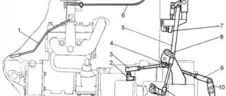
The hydraulic system of the T-25 tractor uses a two-spool four-position distributor P75-B2A. It is installed under the instrument panel on the left and connected by pipelines to the pump and power cylinder of the mounted system. Using the distributor, the mounted system is controlled by supplying working fluid to the upper or lower cavities of the power cylinder.
The distributor spool can be set by the tractor driver using a lever in one of the following four positions (positions): “neutral”, “lifting”, “lowering” and “floating”. The hydraulic distributor diagram is shown in Fig. 69.
Rice. 69. Hydraulic distributor P75 of the T-25 tractor
1 - spool spring; 2 - plug; 3 — clamp spring; 4 — clamp bushing; 5 — clip of clamps; 6 — retainer ball; 7 — booster; 8 - adjusting screw; 9 — booster spring; 10 — booster valve guide; 11 - ball valve; 12 — inclined drilling; 13 — spool; 14 — hydraulic distributor housing; 15 - drain drilling; 16 — spool grooves; 17 - bypass valve; 18 — bypass valve spring; 19 — drain channel; 20 — hole in the shoulder of the bypass valve; 21 - drilling between the bypass and safety valves; 22 - safety valve; 23 — valve holder; 24 - spring; 25 — drain hole into the tank; 26 - spool sleeve.
The T-25 distributor consists of a housing 14, a spool 13 with a locking device, a bypass valve 17, and a safety valve 22. The distributor operates as follows.
Oil from the pump is supplied under pressure to the distributor body through a hole in cavity A. Distributor cavity B is connected to the sub-piston space of the power cylinder, and cavity B is connected to the supra-piston space.
Depending on the position of the spool, both cylinder cavities can be disconnected from the pump and isolated from each other. This corresponds to the neutral position of the hydraulic valve spool P75.
When the spool is in a floating position, both cavities of the hydraulic cylinder are connected to each other, and the oil supplied from the pump is drained into the tank. In this position, oil can flow freely from one cylinder cavity to another, and the piston moves freely under the influence of external forces.
In both cases, the bypass valve is open and allows oil from the pump to flow into the tank. When pumped into cavity B, oil enters under the piston and lifts the tool. At this time, the oil located above the piston is drained through the cavity of distributor B into the tank.
If oil from the pump is supplied to cavity B, then it will enter the space of the cylinder above the piston and lower the implement; in this case, the oil from under the piston through cavity B will drain into the tank.
The bypass valve of the P75 distributor of the T-25 tractor will be closed in these cases. Let us consider in more detail the device and principle of operation of the bypass valve. The bypass valve moves along its axis under the influence of spring 18 and oil pressure from the pump on the valve elements.
The valve dimensions and spring force are selected in such a way that the valve position will be determined by the oil pressure in the cavity G above its shoulder. Oil seeps into this cavity through hole 20 in the collar and through channel 19 enters drilling 15.
If groove 16 (upper or lower) of the spool is located opposite drilling 15, which corresponds to the floating or neutral position, then the oil enters the cavity of the T-25 hydraulic distributor, which is connected to the cavity of the tank and is drained into the tank.
In this case, the oil pressure acting on the end of the valve flange overcomes the force of spring 18 and the valve is in the open state, and the oil entering the distributor from the pump through hole 25 is drained into the tank.
If the spool is installed in such a way that the grooves 16 will not be located against drilling 15, which corresponds to the position of raising or lowering the tool, then the oil from drilling 15 will no longer have an outlet, since this drilling will be blocked by the spool and the pressure in cavity D above the valve shoulder increases to such a value that balances the pressure on the lower end of the bead.
In this case, the forces compressing the spring 18 will decrease and the spring will close the valve, and the oil will flow into the lower or upper cavity of the cylinder and, acting on the piston, will raise or lower the tool.
Operation of the T-25 distributor
The hydraulic valve spool P75 of the T-25 tractor is held in the neutral position by spring 2, which in this position has the greatest height and, therefore, the least force. When the spool moves up or down, the spring is compressed and always strives to set the spool to the neutral position.
As mentioned above, when the spool is in the neutral position, its groove 16 (upper) is located opposite drilling 15 and the oil entering cavity G has access to drain into the tank, so valve 17 is open, and oil from the pump is drained through hole 25 into the tank.
Fittings.
Fittings on hydraulic systems serve several purposes:
For compatibility of different standards such as O-rings for mechanical seal tubes. Allows hydraulic system components to be placed at 45 or 90 degree angles, or straight with a union nut fitting as required. They are designed to be positioned correctly and then tightened as needed. To quickly change equipment. Quick installation and replacement in the machine without changing hoses or valves.
Tractor T-25
Hydraulic distributors
The hydraulic system distributor is used to distribute the flow of working fluid supplied by the pump between consumers (power cylinders and hydraulic motors), to automatically switch the system to idle (bypassing the working fluid into the tank) during periods when all consumers are turned off, and to limit the pressure in the hydraulic system when random overloads. GOST 8751-58 provides for four standard sizes of distributors with a capacity of 25, 75, 150 and 300 l/min. Since 1962, distributors have been produced with ball fixation: three-spool valves R75-VZ and two-spool valves R75-B2. Letters and numbers mean:
- P - distributor
- B - type of spool, which has fixation of the “Lifting”, “Forced Lowering” and “Floating” positions, as well as automatic return from the “Lifting” and “Forced Lowering” positions
- 75 - maximum flow rate in l/min
- 2 and 3 - number of spools
A three-spool valve allows for separate control of three consumers (power cylinders and hydraulic motors), and a two-spool valve allows for separate control of two consumers.
Since 1967, instead of distributors P75-VZ and P75-B2, the industry has produced new models with index A, i.e. P75-VZ-A and P75-B2-A. These distributors feature improved bypass valve and control components. The design of the bypass valve and its seat remains the same, but the remaining parts of this assembly are changed or removed from the new design of the bypass valve assembly.
Rice. Distributor bypass valve assembly R75-VZ-A: 1 — bypass valve spring; 2 — spring washer; 3 - emphasis; 4 — stop gasket; 5 - bolt; 6 — sealing ring; 7 — valve guide; 8 — bypass valve.
The guide and plug of the bypass valve assembly of the P75-VZ-A distributor are combined into one part, so the length of the guide 7 has become shorter and is located entirely in the distributor body, which simplifies the design of the stop 3 of the bypass valve.
The spherical part of the guide rests against the cover (stop) 3. A paronite gasket 4 is installed between the distributor body and the cover 3, which has a larger width of the sealing part than in the P75-B distributor. Spring 1 of the bypass valve and bolts 5 for securing the cover are shorter.
To prevent the flow of working fluid from the pressure line into the cavity above the spherical part, the guide 7 of the bypass valve has a rubber sealing ring 6. A hole is drilled in the spherical part of the guide, which serves to drain leaks from the cavity above the spherical surface of the guide into the distributor drain line through the axial hole of the valve 8 In addition, this hole can be used when dismantling the valve.
Since the guide 7 can self-align, the possibility of the bypass valve sticking is significantly reduced.
The new control unit differs from the previous design in the absence of an axis for attaching the levers 12 in the top cover and their sealing device.
In the axleless design, the lever sphere rests on two liners 11 and 9, which have an inner spherical and outer cylindrical surface. A rubber o-ring 10 is installed between the liners. In the old design it was located behind the center of the lever sphere, closer to the plane of the cover, and now it is on the other side of the sphere. In this case, the pressure of the working fluid on the sphere helps to improve the seal. The upper liner 9 rests with its end against the ring plate, and the bottom liner 11 rests against the bottom of the cylindrical recess in the cover 13.
Rice. Distributor control unit Р75-ВЗ-А: 1 — spring washer; 2 - bolt; 3 — segmental key; 4 — spring washer; 5 — handle cap; 6 — dust; 7 — anther plate; 8 — ring plate; 9 — upper liner; 10 — sealing ring (27X3); 11 — lower liner; 12 — lever; 13 — top cover.
Three or two corrugated boots 6 of the previous design are installed on top of the ring plate 8. The bases of the anthers are pressed against another plate 7 of the anthers. Both plates 8 and 7 are attached to the cover using eight or six bolts 2 (for R75-VZ-A and R75-V2-A, respectively). The lever is secured against rotation using flats on a small sphere that fit tightly to the walls of the hole in the spool.
The small sphere of the lever and the hole in the lever for this sphere are 3 mm larger in size than in the old distributors R75-VZ and R75-B2. In this regard, the length of the spool in the new distributors (P75-VZ-A and P75-B2-A) has increased.
To replace a worn out sealing ring 10, you need to unscrew the bolts 2 securing the plates, remove the plate 7 of the anthers, then pass the plate 8 of the rings through the bases of the anthers 6 and remove it, and then remove the lever along with the outer liner. Now you can replace the rubber ring 10, which has dimensions of 27X3 mm. Reassembling the control unit is carried out in the reverse order. The new control unit is more durable due to the introduction of self-sealing of the sphere and the elimination of elements that contribute to wear of the unit.
In distributors with the letter “A” the design of the plugs has been changed. On each plug, between the end and the groove for the rubber ring, there is a collar to protect the ring itself from being squeezed out when the plug is unscrewed.
The P150 distributors are made according to the same design scheme as the P75-VZ distributors, but with a larger capacity (150 l/min) and greater weight (35 kg).
The spool valves of the P150-VZ distributors produced by the Chelyabinsk Tractor Plant (ChTZ) have a diameter of 35 mm, and those produced by the Leningrad Plant named after. Kirov (LKZ) - 32 mm. They are divided into 20 size groups every 5 microns.
Rice. Distributor: R150-VZ: 1 — lock nut; 2 - adjusting screw; 3 — valve spring; 4 - valve guide; 5 - safety valve; 6 — safety valve socket; 7 — spool control lever; 8 - fitting; 9 - bypass valve; 10 — bypass valve socket; 11 — bottom cover; 12 — spool spring; 13 — spool; 14 — body; 15 — top cover; 16 - sealing ring; 17 — guide bushing of the bypass valve; 18 — bypass valve spring; 19 — ball valve; 20 — booster; 21 - pusher; 22 — booster spring; 23 — retainer clip; 24 — adjusting nut; 25 — upper spring support washer; 26 — retaining ball; 27 — bushing of clamps; 28 — clamp spring; 29 — lower spring support washer; 30 — adjusting nut rod.
The P150-VZ distributors differ from the P75-VZ distributors in the design of the safety valve, the design of the automatic spool return sensor, and the design features of the housing and distributor caps. Technical characteristics of the distributors are given in the table.
Table. Technical characteristics of distributors
| Indicators | Distributor brands | ||
| P75-B2-A | R75-VZ-L | PI50-B3 | |
| Distributor type | Valve-spool | ||
| Maximum throughput, l/min | 75 | 75 | 150 |
| Safety valve type | Differential constant pressure | ||
| Number of spools | 2 | 3 | 3 |
| Number of positions (positions) | Four: "Lift", "Forced Lower", "Floating" and "Neutral" | ||
| Fixation of spool valves in the “Lifting”, “Lowering”, “Forced” and “Floating” | Using a ball lock | ||
| Returning spools from the “Lifting” and “Forced Lowering” positions | Automatic, when the specified pressure is reached in the system | ||
| Returning spools from the “Floating” position | Manual | ||
| Number of separately controlled cylinders (hydraulic motors) or groups of cylinders (groups of hydraulic motors) | 2 | 3 | 3 |
| Automatic device response pressure return of spools to neutral position, MPa (kgf/cm2) | 11 — 12,5(110—125) | 11 — 12,5(110—125) | 10,5—12(105—120) |
| response pressure , 2 MPa (kgf/cm) | 13—13,5(130—135) | 13—13,5(130—135) | 13—13,5(130—135) |
| Resistance to bypass the working fluid with the neutral position of the spools, MPa (kgf/cm2) | No more than 0.3 (3) | ||
| Weight, kg | 10,1 | 15,5 | 30,2 |
| Tractors that install distributors | T-25, T-16 | T-28, T-54S, T-74, DT-75 | T-J30, K-700 |
The design differences and features of the above components of the P150-VZ distributor from the P75-VZ distributor are as follows. Socket 6 of the safety valve in the middle part along its length has a circular recess through which working fluid is supplied from the valved cavity of the bypass valve through a drilling (bypass channel) in the distributor body and through drillings in socket 6 to valve 5. Socket 6 is screwed into the distributor body from the outside and sealed on both sides with rubber rings, which are installed to prevent leakage of the working fluid from the annular recess of the socket to the outside and into the drain cavity of the distributor.
The fixing mechanism and unloading channels of the P150-VZ spool are the same as in the P75-VZ spool, but the design of the automatic return device sensor is similar to the design of the P40/75 distributor sensor. A steel seat is pressed into the axial hole of the spool, in which there is an outer annular groove and radial drillings for supplying working fluid from the pressure cavity of the distributor to valve 19. The valve is pressed to the hole in the seat using the booster spring 22 through booster 20 and pusher 21.
The booster spring 22 from below rests on the adjusting screw-nut 24, into the hole of which the adjusting rod 30 enters, passing through the sleeve 27 of the clamps and the spring 28.
The actuation pressure of the automatic return of the spool is 10.5–12 MPa (105–120 kgf/cm2) and is achieved by turning the adjusting rod 30, rotating the adjusting screw-nut and compressing the spring 28 clamps. After adjustment, rod 30 is locked with a cotter pin, which passes through the slot and the spool plug. In this case, the rod 30 can move in the axial direction.
Under the influence of increasing pressure of the working fluid in the axial channel of the spool, valve 19 moves away from the socket, and then booster 20 and pusher 21 move down. The latter rests on the end of the adjusting rod 30 and drives the sleeve 27 of the clamps, compressing the spring 28.
The retainer sleeve, having moved downwards, releases the retainer balls 26, which will come out of the cage, and the spool 13, under the action of the spring 12, compressed between the two cups, returns to the neutral position. The working fluid that has passed through the gap between the spool and the booster is drained through the holes in the spool into the drain cavity of the bottom cover.
In the distributor housing 14 there are eight outlet holes and two pressure holes, in which an M39X15 mm thread is cut for screwing in the fittings, and two through holes are drilled, which serve to connect the cavities of the upper and lower covers.
The distributor body and both covers are made of cast iron. Paronite gaskets are laid between the housing and the covers to seal the connectors. The bottom cover 11 has bosses with holes for attaching the distributor, which is installed only in a vertical position.
The working fluid is drained from the distributor through one of the two side rectangular holes in the bottom cover. The second hole is closed with a plate, which is fixed to the lower cover of the distributor with four bolts and sealed with a paronite gasket. The top cover of the distributor also has a terminal that serves to connect to the working fluid tank using a special tube.
The control valve spools of the P150-VZ distributor are placed in the top cover and have axial fastening of the control levers, similar to the design of this unit of the P75-VZ distributor. It differs from the latter in that there are no plate-shaped boots, and each corrugated boot is attached to the cover using a separate round plate and three screws passing through the corresponding holes in the boot and plate.
The distributor of the K-700 tractor (LKZ design) differs from the distributor of the T-100M tractor in that the body is slightly longer due to the presence of cavities closed by a special plate with a paronite seal and screwed to the body with six bolts. Spool diameter 32 mm. The P150-VZ distributor manufactured by LKZ since 1967 has a control of an axleless design, similar to that used in the P75-VZ-A distributor.
The P150-VZ distributors installed on the T-100M and K-700 tractors for industrial use do not have sensors for the automatic spool return device.
ON THIS TOPIC:
- Hydraulic system malfunction due to distributor failure